Viadotto Rabbi

Rabbi viaduct

Project for the launch of the bridge.

Category: Road bridges
Services: Executive design
Period: July 2021 – August 2022
Client: IDRO.STRADE S.r.l
Viadotto Rabbi

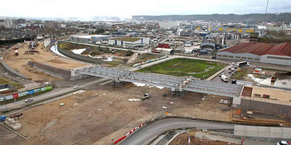
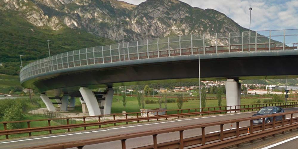
The viaduct over the Rabbi river is included in the section Km 1+930.59 and Km 2+141.67 of the new ring road system of Forlì, connecting the ring road East – Lot 3.
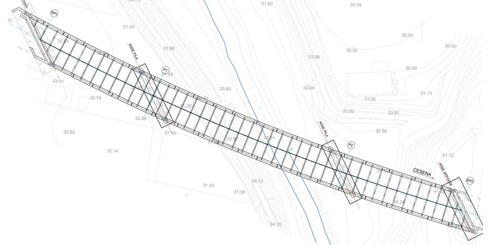
The work consists of a bridge over 3 spans of spans equal to 58.58, 94.30 and 58.20 m; it houses a road platform with a constant width of 10.5 m and two side curbs, on which a road safety barrier is mounted, with a width of 0.75 m; in addition to the curbs, there is a net space of 0.95 m used as a service sidewalk.

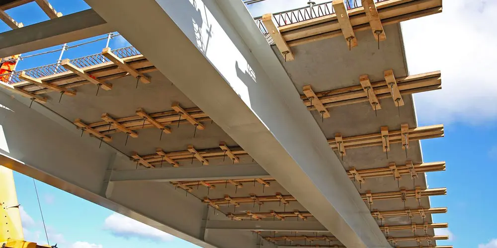
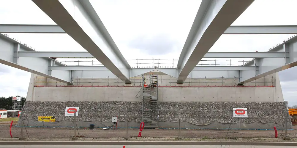
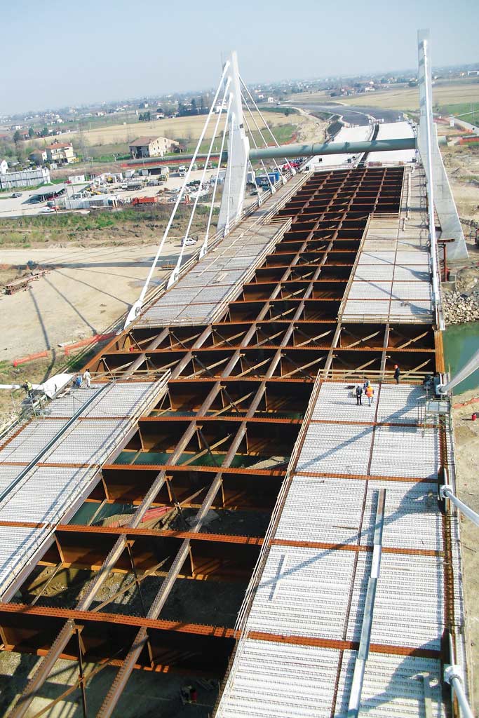
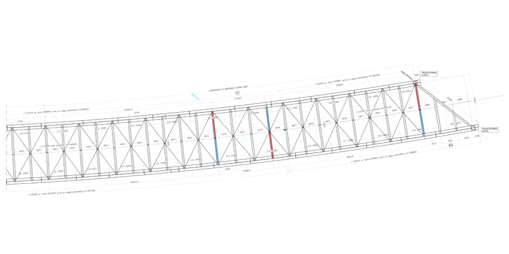
The structure consists of a grid of steel beams with two main beams arranged parallel along the development axis of the viaduct and by crosspieces orthogonal to the main beams with a regular pitch of about 5 m on which rests a roadway slab with a thickness equal to 21cm + 6cm of predalles. The two main metal beams have a double T cross section of variable height from 4 m (lowest value recorded in the span) up to 6.00 m (maximum value recorded in axis with the pile).
The bridge has 2 central reinforced concrete piers in which allow the Rabbi River to be crossed with the maximum span and two traditional reinforced concrete abutments.
The foundations of piers and abutments are made using 120 cm diameter piles with a length of 28 m for the abutments and 100 cm diameter piles and 30 m long for the piles.

Viadotto Rabbi
Viadotto Rabbi

The structure consists of a grid of steel beams with two main beams arranged parallel along the development axis of the viaduct and by crosspieces orthogonal to the main beams with a regular pitch of about 5 m on which rests a roadway slab with a thickness equal to 21cm + 6cm of predalles. The two main metal beams have a double T cross section of variable height from 4 m (lowest value recorded in the span) up to 6.00 m (maximum value recorded in axis with the pile).
The bridge has 2 central reinforced concrete piers in which allow the Rabbi River to be crossed with the maximum span and two traditional reinforced concrete abutments.
The foundations of piers and abutments are made using 120 cm diameter piles with a length of 28 m for the abutments and 100 cm diameter piles and 30 m long for the piles.

Viadotto Rabbi
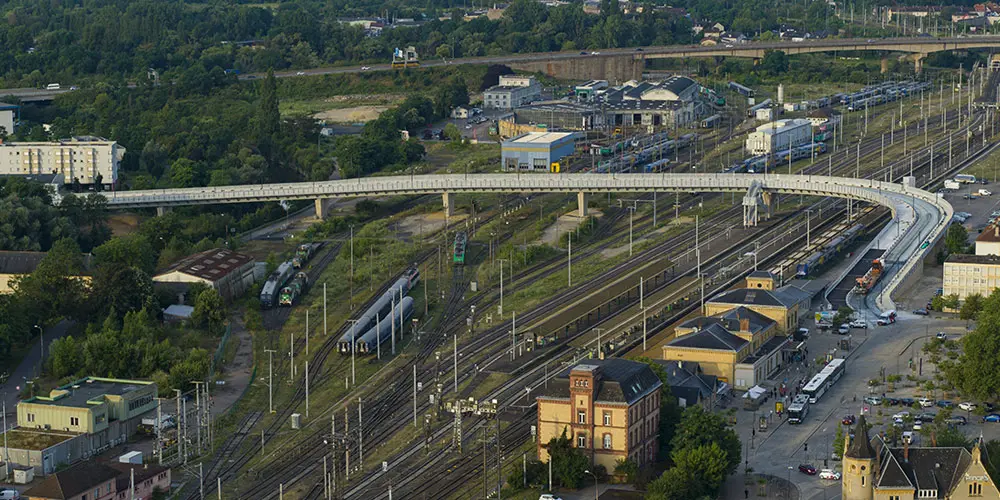
Ponte di Thionville

Thionville bridge

Project of the Thionville Bridge.

Category: Road bridges
Services: Final design
Period: October 2021 – April 2022
Client: Smitu Thionville Fensch

Ponte di Thionville

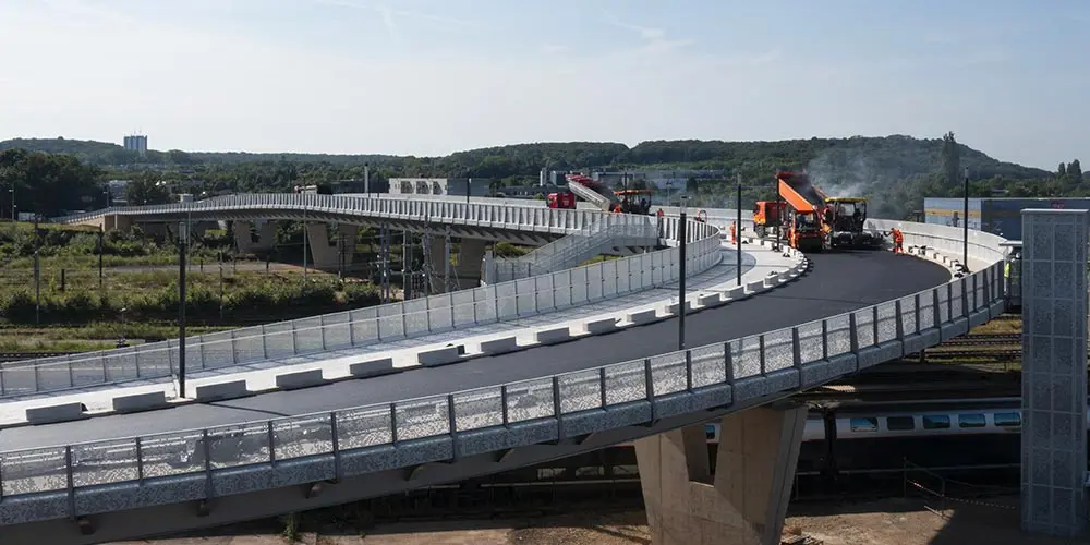
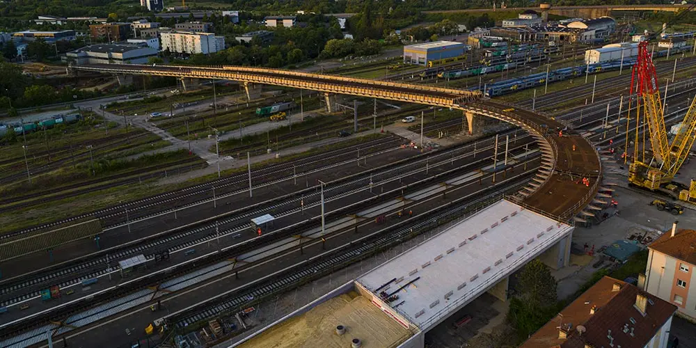
The main structure has a total length of approximately 309 meters and consists of two separate decks. The first deck “(C0-P2” has a plan layout with a radius of curvature of 50.0m and develops over two spans of 34m + 52 m for a total length of 86 m. The deck “P2-C7” has a rectilinear route over 5 spans (58 + 42 + 39 + 48.5 +34 m) for a length of 222 m.
The platform has a total width of approximately 16m, divided into a central part of 7.00 meters wide for the BHLS, a cycle-pedestrian path 5.00 meters wide and 1 sidewalk 2.45 meters wide.

The 1.89 m high cross section is made by a metal box with four webs. Metal slabs lean on the upper flanges and have the function of permanent formwork for the rounding of a reinforced concrete slab 27 cm thick.
The connection between footings and slab is ensured by rungs. The reinforced concrete slabs located on the overhangs are made by prefabricated semi-slabs with concreting completely on site. The overhangs are supported by variable-height steel brackets located in correspondence of the standard struts and bridge parts.

The overall weight is approximately 2000 tonnes, of which 600 relate to the curved section alone.
Two laminated elastomer bearings are located on all the piers or abutments; the C0-P2 deck in correspondence of the alignments P2 and C0 on the curved internal side, has special anti-lifting bearings.

Ponte di Thionville
Ponte di Thionville
Ponte di Rouen

Rouen bridges

Executive design and assembly of steel bridges.

Category: Road bridges
Services: Executive design
Period: March 2021 – July 2022
Client: BIT S.p.a.

Ponte di Rouen

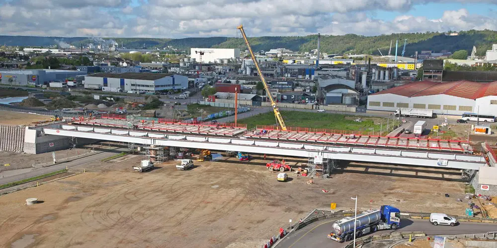
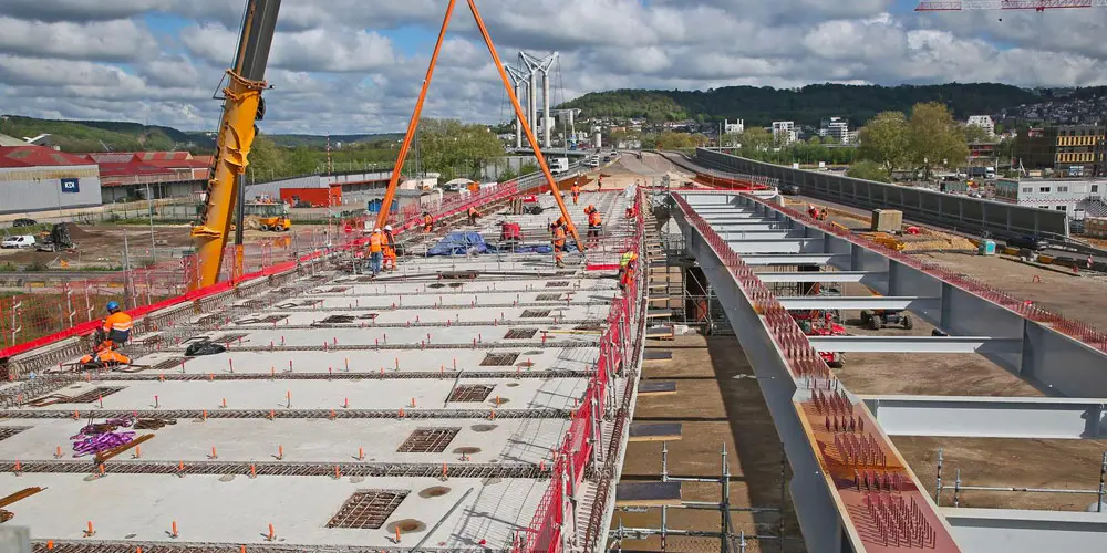
The works include the creation of approximately 1.1 km of expressway between the Stalingrad interchange of the current South III expressway and the left bank access viaduct to the Flaubert bridge.

Ponte di Rouen

The works include the creation of approximately 1.1 km of expressway between the Stalingrad interchange of the current South III expressway and the left bank access viaduct to the Flaubert bridge.

This new portion notably includes three reinforced soil embankments and two engineering structures, including a railway crossing.
The Madagascar structure consists of two separate decks: the east deck is 13.50 m wide and the west deck is 12.68 m wide. The total length is 116 m over 3 spans 36 m + 44 m + 36 m.

Ponte di Rouen
Ponte di Rouen

This new portion notably includes three reinforced soil embankments and two engineering structures, including a railway crossing.
The Madagascar structure consists of two separate decks: the east deck is 13.50 m wide and the west deck is 12.68 m wide. The total length is 116 m over 3 spans 36 m + 44 m + 36 m.

Ponte di Rouen

The layout is partly straight and partly curved; the longitudinal profile is a ramp with a constant slope. Each deck is made up of 2 metal beams 1.70 m high; the metal beams are reconstituted welded profiles.
The beams are connected to a fully prefabricated reinforced concrete slab 30 cm thick. Each beam rests on a laminated elastomer bearing. Four of the metal spacers are used.

Common type except C5-C6, C11 and C12, C5-C6, C11 and C12 type (before and after pier spacers), pier type and abutment type. The framework of the deck will be assembled on site and then moved by SPMT and, finally, set up by crane using pairs of cranes. Once the deck has been placed on temporary supports, the prefabricated slabs will be put in place. The deck will be completed by concreting the keying strips and completely deck finishes and equipment.

Ponte di Rouen
Ponte di Rouen

Common type except C5-C6, C11 and C12, C5-C6, C11 and C12 type (before and after pier spacers), pier type and abutment type. The framework of the deck will be assembled on site and then moved by SPMT and, finally, set up by crane using pairs of cranes. Once the deck has been placed on temporary supports, the prefabricated slabs will be put in place. The deck will be completed by concreting the keying strips and completely deck finishes and equipment.

Shopping center “Caselle Open Mall” – Viaducts Roundabout 1 and 2 and railway overpass

Final design of bridge substructures.

Category: Piers and abutments
Services: Final detailed design
Period: September 2018 – October 2019
Client: R&P Engineering s.r.l.
Amount: Viaduct over Roundabout 1 – 4.145.582,07 € S04 (IXb )
Viaduct over Roundabout 2 – 2.210.702,40 € S04 (IXb )
Railway overpass – 1.648.114,38 € S04 (IXb )
Final detail design of the retaining walls of the access ramps – 1.765.554,19 € S03 (Ig)
Final detailed design of the sheet piling retaining wall for the railway overpass 502.136,94 € S05 (IXc)

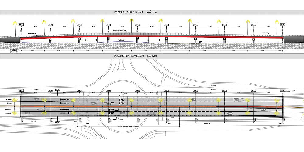
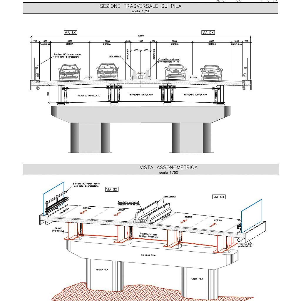
The Viaduct over Rotatoria 1 has a deck of constant width 19.8 [m], with two carriageways of 8.25 [m] made with 4 beams on 9 spans, with a span of 27.5 [m], for a total length of 247.5 [m] approximately.

The Viaduct over Rotatoria 1 has a deck of constant width 19.8 [m], with two carriageways of 8.25 [m] made with 4 beams on 9 spans, with a span of 27.5 [m], for a total length of 247.5 [m] approximately.

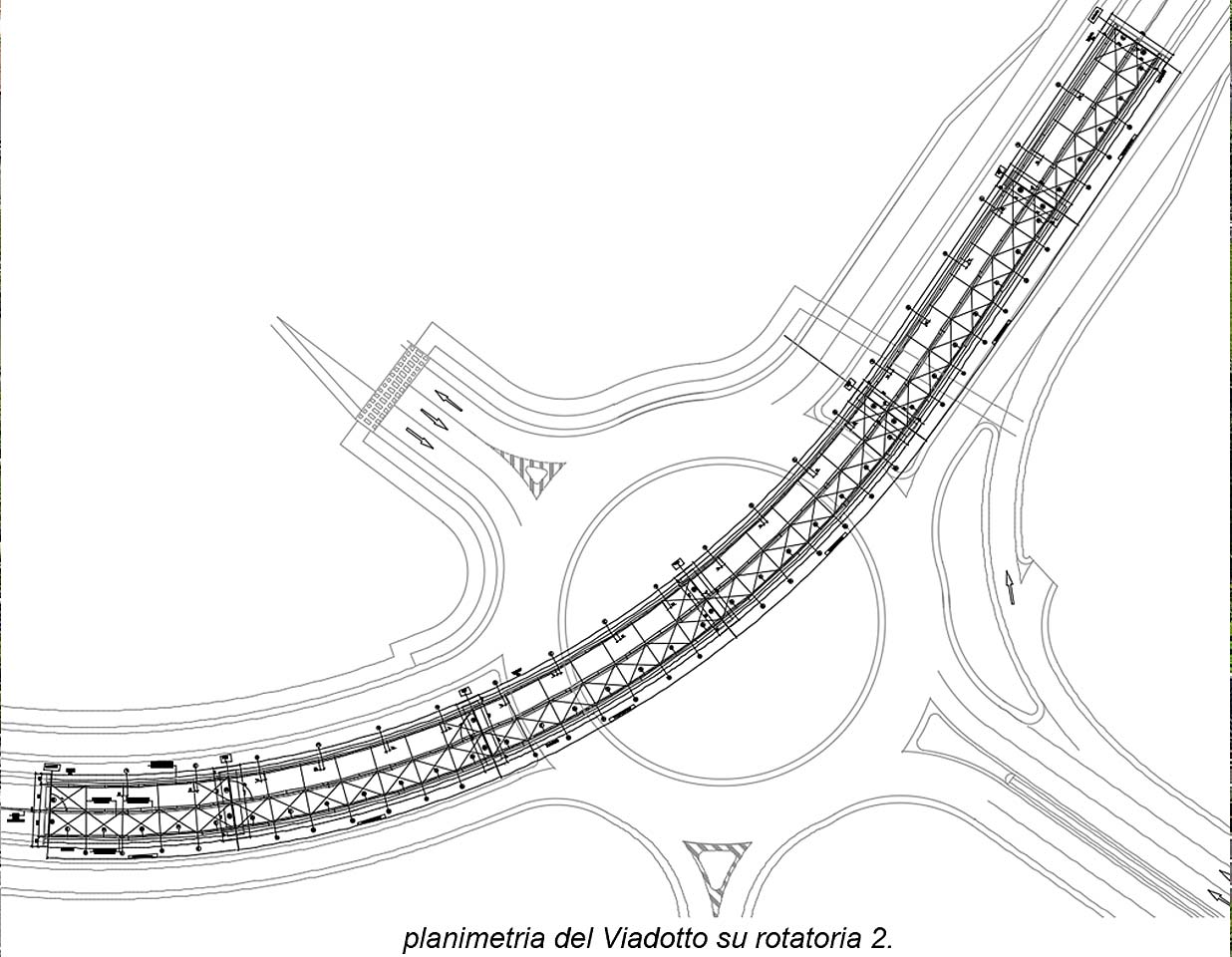
The Viaduct on Rotatoria 2 has a 11.1 [m] wide deck with a 9.60 [m] carriageway supported by 3 beams on 6 spans, with a span of 28 [m] in the two side spans and 40 [m] in the four central spans, for an overall length of approximately 216 [m].
The overpass has a 11.5m carriageway and a deck made with 9 side-by-side beams over a span of 43 [m].

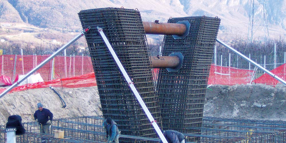
The piers and supporting abutments of the viaduct have shallow foundations, in consideration of the good mechanical characteristics of the surface soil. In elevation, the pies have a rectangular section shaft with rounded heads with a rectangular section pier cap of variable height. The abutments are of the traditional type with wing walls to contain the road embankment.

The piers and supporting abutments of the viaduct have shallow foundations, in consideration of the good mechanical characteristics of the surface soil. In elevation, the pies have a rectangular section shaft with rounded heads with a rectangular section pier cap of variable height. The abutments are of the traditional type with wing walls to contain the road embankment.

Trento South A22 Motorway

Design of the piers and abutments for the viaduct “Piste di Stazione”.

Category: Piers and abutments
Services: Final detailed design
Period: July 2007 – December 2007
Client: Seteco Ingegneria s.r.l. Coger s.p.a.

Junction viaduct envisaged as part of the works for the construction of the Trento Sud station consisting of 9 spans with a length of 35.0 x 4 + 47.5 + 35.0 x 4 for a total length of 327.50 m. The viaduct is built with a closed box section in a mixed steel-concrete solution, with a deck width of 16.00 m and consisting of two carriageways with a width of 6.95 m. The piers are framed and the abutments are of the traditional type, both with deep foundations on piles.
Junction viaduct envisaged as part of the works for the construction of the Trento Sud station consisting of 9 spans with a length of 35.0 x 4 + 47.5 + 35.0 x 4 for a total length of 327.50 m. The viaduct is built with a closed box section in a mixed steel-concrete solution, with a deck width of 16.00 m and consisting of two carriageways with a width of 6.95 m. The piers are framed and the abutments are of the traditional type, both with deep foundations on piles.

Shopping centre “Caselle Open Mall”

Final design of the foundations of the buildings of the shopping centre.

Category: Building foundations
Services: Final detailed design
Period: January 2019 – July 2020
Client: R&P Engineering s.r.l.

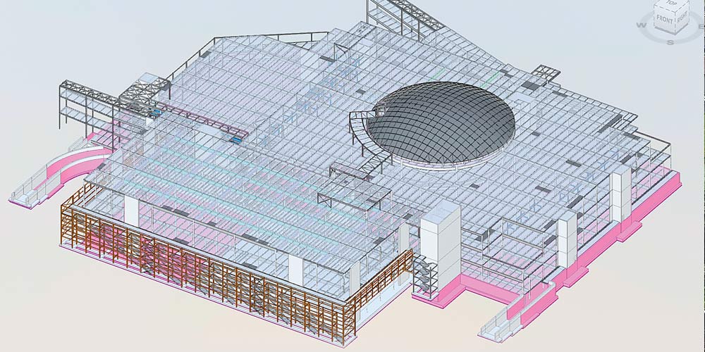
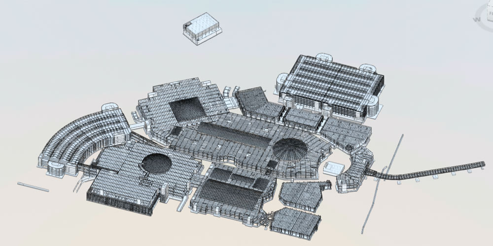
Design of the buildings forming part of the «Caselle open Mall» complex, a newly built shopping centre located in the municipality of Caselle. The group of multi-storey commercial buildings is represented by the components of the “Village”, i.e. Blocks A, B, C, D, E. The Village area is then directly connected to the other two commercial macro-areas called “Food Court” (Block N) and the Premium (Block M).
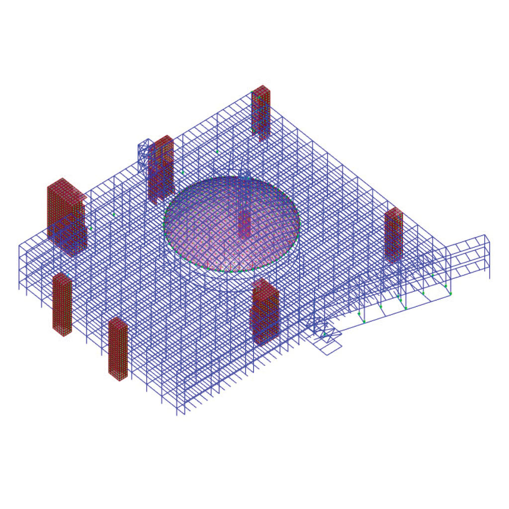
The static structural scheme is common for all the buildings making up the Village: they are all made up of steel beams and columns of the pendular type, braced with RC cores and walls.

The foundations of all the buildings are shallow and consist of a grating of inverted beams with a rectangular section between 1 and 1.5 m in height, connected by a 30 cm thick slab. The foundations of the cores are slabs with a thickness equal to that of the connected inverted beams. The evaluation of the elastic constants of the soil in dynamic conditions was carried out according to the Gazetas formulation. The pressure of the soil on the retaining walls was evaluated according to Wood’s theory.

The foundations of all the buildings are shallow and consist of a grating of inverted beams with a rectangular section between 1 and 1.5 m in height, connected by a 30 cm thick slab. The foundations of the cores are slabs with a thickness equal to that of the connected inverted beams. The evaluation of the elastic constants of the soil in dynamic conditions was carried out according to the Gazetas formulation. The pressure of the soil on the retaining walls was evaluated according to Wood’s theory.

Bridge over the Bacchiglione river

Design of the elevation structures of the reinforced concrete mats for the cable-stayed bridge over the river Bacchiglione.

Category: Pylons and mats
Services: Design for construction
Period: September 2009 – March 2010
Client: Seteco Ingegneria s.r.l. , Serenissima Costruzioni s.p.a.
Amount: approximately € 1,150,000.00 (Category Ig)

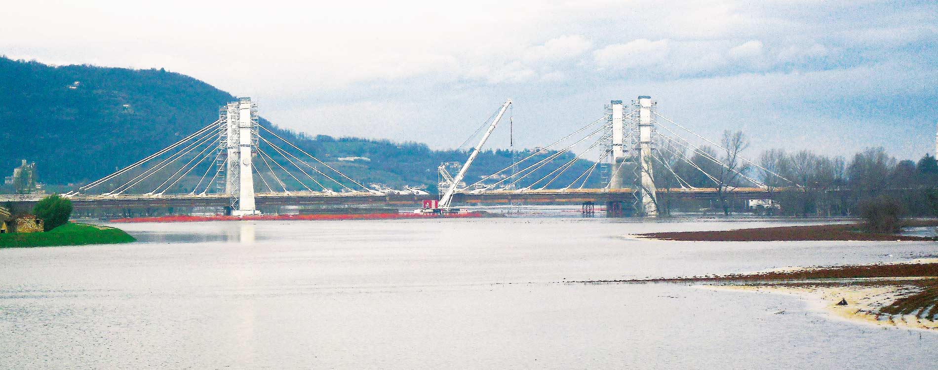
This work is carried out as part of the completion of the A31 “Valdastico” motorway to the south, in the section between Vicenza and Rovigo (from km. 6 + 041 to km. 6 + 573).

This work is carried out as part of the completion of the A31 “Valdastico” motorway to the south, in the section between Vicenza and Rovigo (from km. 6 + 041 to km. 6 + 573).

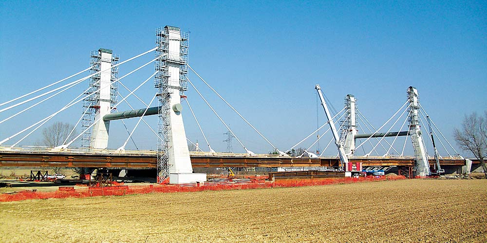
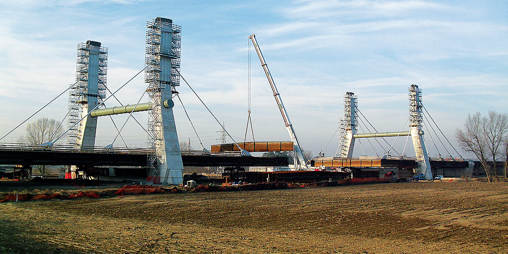
The two pylons, one on the side towards Vicenza and the other on the side towards Rovigo, support two lateral spans of 62 m and a central one with a 140 m span by means of cable stays.

The two pylons, one on the side towards Vicenza and the other on the side towards Rovigo, support two lateral spans of 62 m and a central one with a 140 m span by means of cable stays.

The two antennas have an “H” frame shape and are made of reinforced concrete up to a height of about 31.5 m from the ground level; beyond this height, corresponding to the intrados of the upper crosspiece, in metal tube, they extend for a further height of 19m and are made with two steel sections connected by a steel transverse beam.

The two antennas have an “H” frame shape and are made of reinforced concrete up to a height of about 31.5 m from the ground level; beyond this height, corresponding to the intrados of the upper crosspiece, in metal tube, they extend for a further height of 19m and are made with two steel sections connected by a steel transverse beam.

Bridge over the canal Naviglio Grande

Design of the reinforced concrete abutments for the arch bridge on the Naviglio Grande.

Category: Piers and abutments
Services: Final detailed design
Period: January 2005 – November 2007
Client: Seteco Ingegneria s.r.l.; CAV TO-MI Consortium
Amount: € 5,228,869.25 (Category IX b) € 927,639.84 (Category I g)

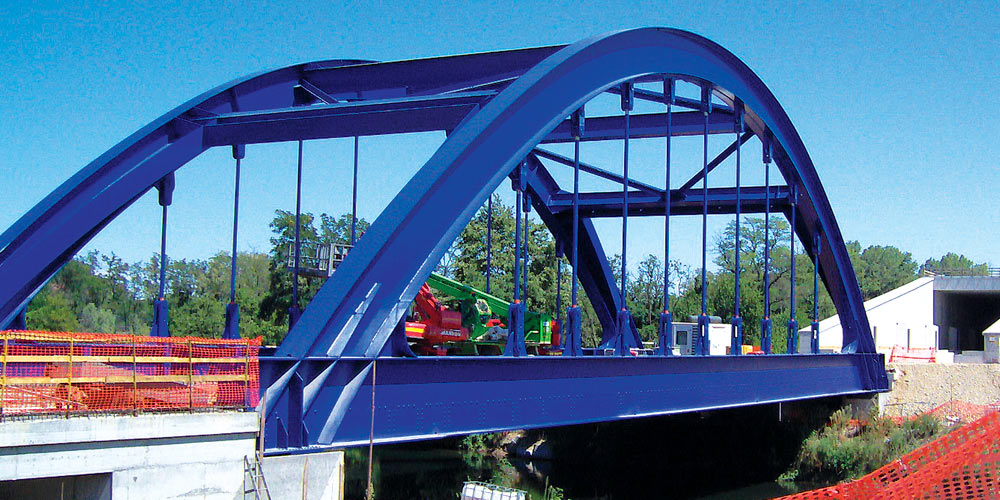
Executive design of the reinforced concrete abutments to support the arched railway deck. The abutment SP1 (fixed) is of the box-like type for the passage of the viability along the canal Naviglio Grande and has a longitudinal length of over 10 m and a width of 16 m.

Executive design of the reinforced concrete abutments to support the arched railway deck. The abutment SP1 (fixed) is of the box-like type for the passage of the viability along the canal Naviglio Grande and has a longitudinal length of over 10 m and a width of 16 m.

The SP2 abutment (free) is of the traditional type and extends longitudinally for about 6m while the width is identical to that of the SP1 abutment. Both substructures have shallow foundations. The design also involved the provisional works carried out for the construction phases of the abutments, for example Larsen-type sheet piling.

The SP2 abutment (free) is of the traditional type and extends longitudinally for about 6m while the width is identical to that of the SP1 abutment. Both substructures have shallow foundations. The design also involved the provisional works carried out for the construction phases of the abutments, for example Larsen-type sheet piling.

Bridge over the Polcevera – Campasso torrent

Project of decks and piers and abutments on the line - Parco Campasso at km 4+328.

Category: Railway Bridges
Activity: Detailed design
Period:February 2004 – December 2004
Client: Seteco Ingegneria s.r.l.
Value:€11,498,353.59 (Category IX b) €2,934,378.25 (Category I g)

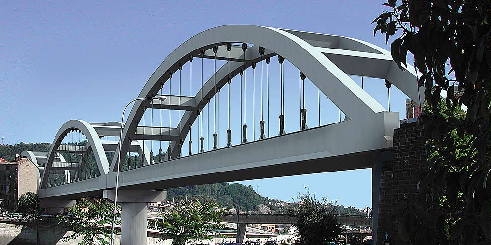
Railway bridge over the Polcevera torrent, near the Rivarolo railway station (Genoa), consisting of 3 single-supported spans with arched metal deck spanning 78.5m, oblique deck with cast-in-place slab 15m wide. The section of the piles is circular, the foundations are of the well-type.

Railway bridge over the Polcevera torrent, near the Rivarolo railway station (Genoa), consisting of 3 single-supported spans with arched metal deck spanning 78.5m, oblique deck with cast-in-place slab 15m wide. The section of the piles is circular, the foundations are of the well-type.

Bridge over Largo Jurse

Project of metal decks for the Conigliano-Sanpierdarena line at km0+159m.

Category: Railway Bridges
Activity: Pre-design
Period: February 2004 – December 2004
Client: Seteco Ingegneria s.r.l.
Value: €11,498,353.59 (Category IX b) €2,934,378.25 (Category I g)

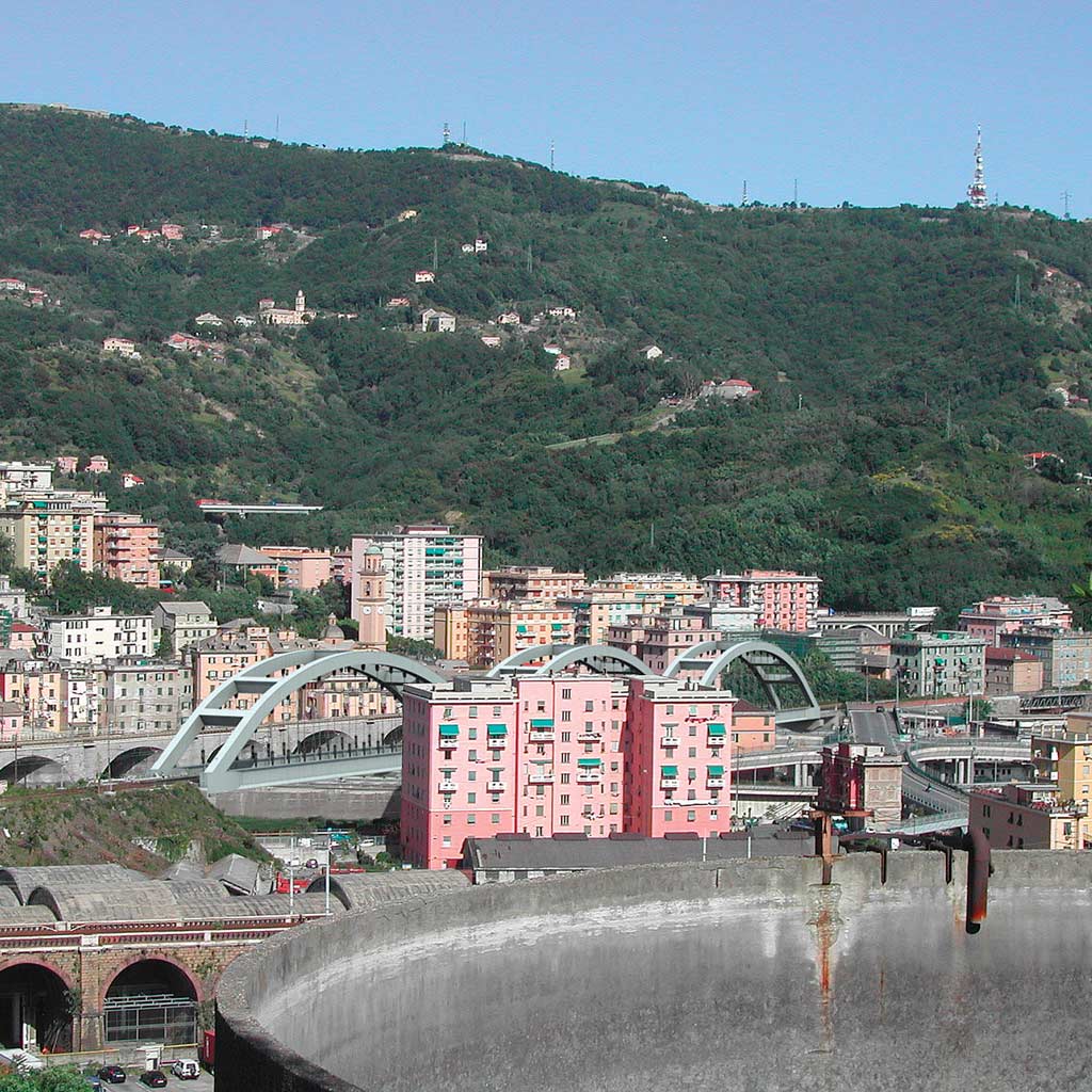
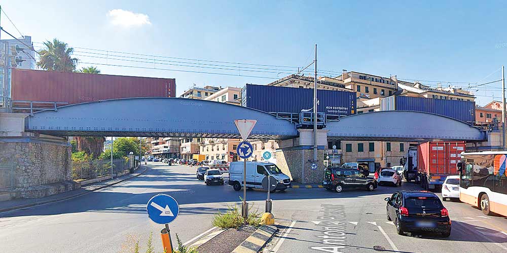
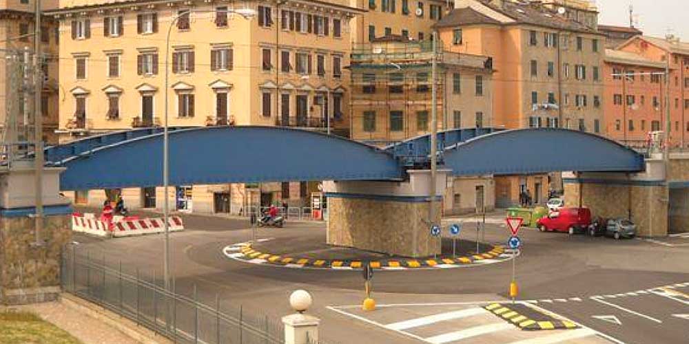
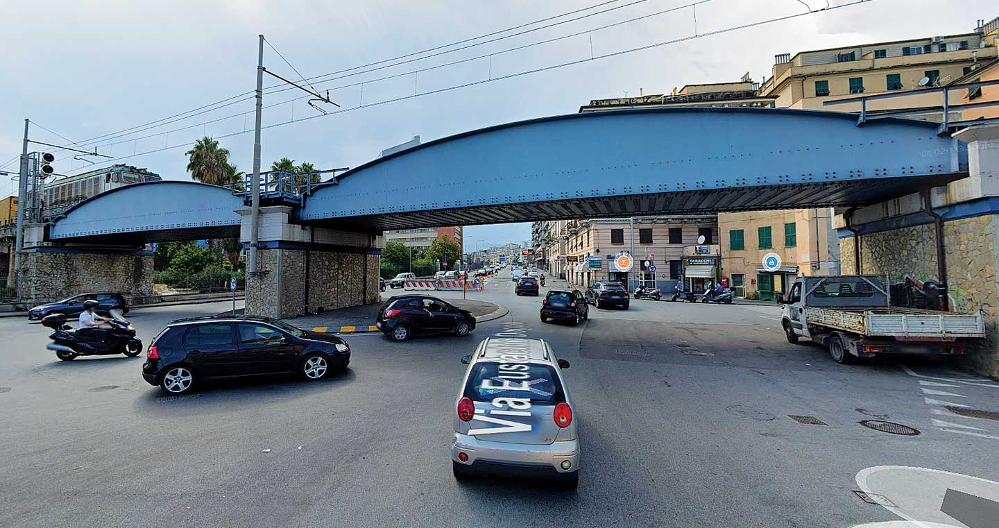
Pre-design of the new railway bridge to replace the existing bridge at Km 0 +159 and 0 + 179 of the Cornigliano – Sampierdarena line. The structural scheme is a solid web girder with a through-bridge scheme. The bridge has two equal spans of 22.5m; the beams are spaced by 5.35m.

Pre-design of the new railway bridge to replace the existing bridge at Km 0 +159 and 0 + 179 of the Cornigliano – Sampierdarena line. The structural scheme is a solid web girder with a through-bridge scheme. The bridge has two equal spans of 22.5m; the beams are spaced by 5.35m.

The main I-section beams have variable height with a layout as a segment of a circle (maximum height 2900mm, minimum 1135mm on the supports). The support plan for the railway slab is made of HE beams with 0.5 m spacing embedded in the concrete casting with a minimum thickness of 40 cm.

The main I-section beams have variable height with a layout as a segment of a circle (maximum height 2900mm, minimum 1135mm on the supports). The support plan for the railway slab is made of HE beams with 0.5 m spacing embedded in the concrete casting with a minimum thickness of 40 cm.