Executive design and assembly of steel bridges.
Category: Road Bridges
Activity: Detailed design
Period: May 2019 – December 2020
Client: Bit s.p.a.
Value: 3.082.329,96 € S04 (IXb)
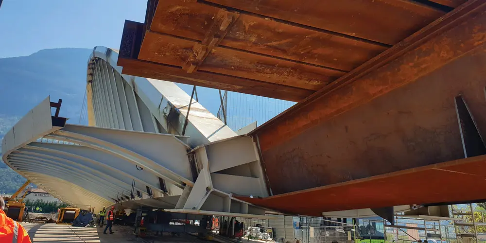
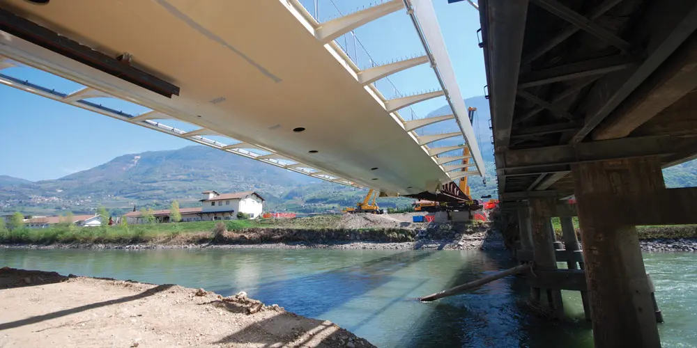
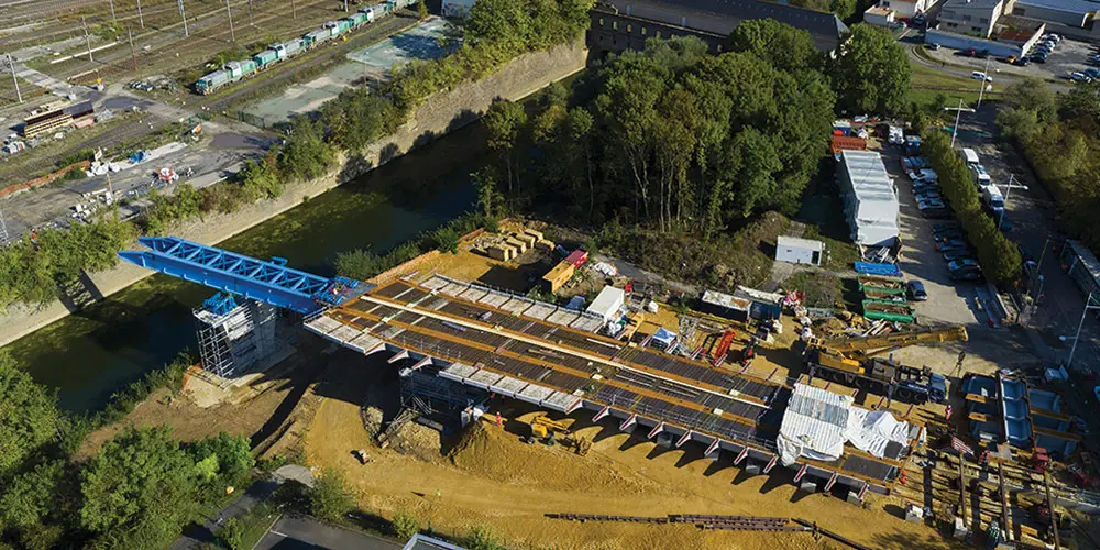
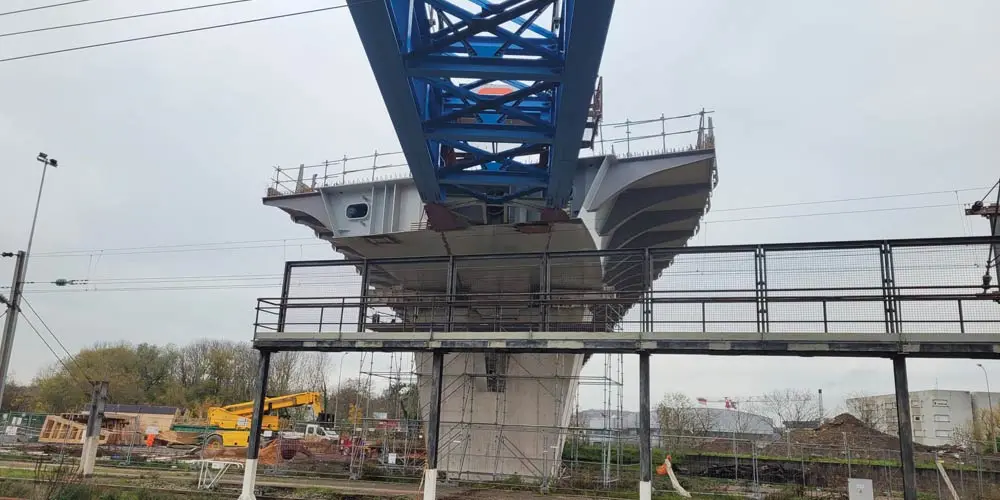
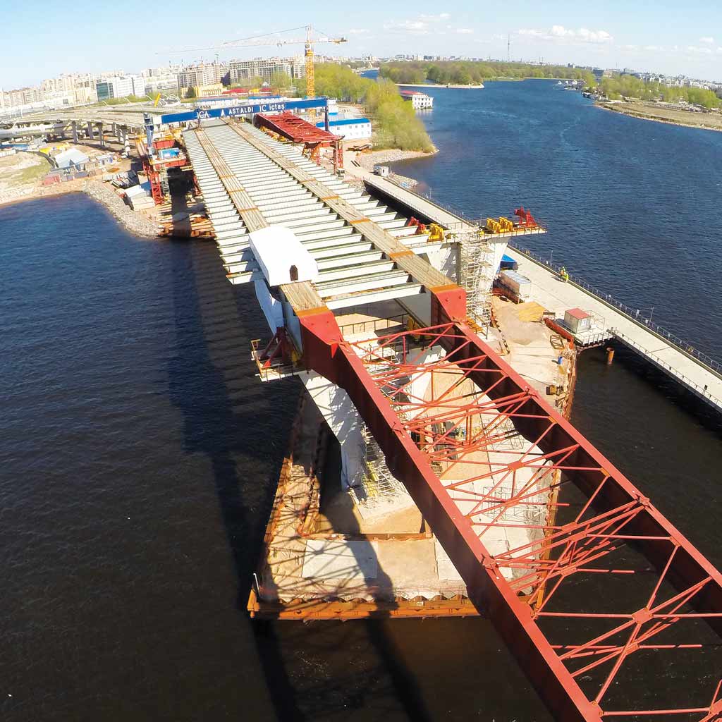
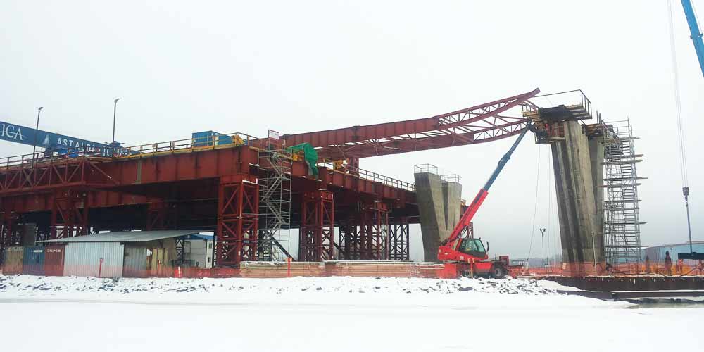
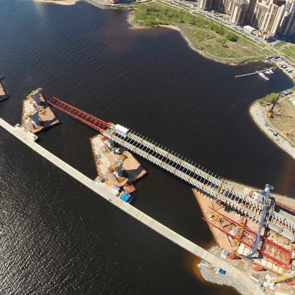
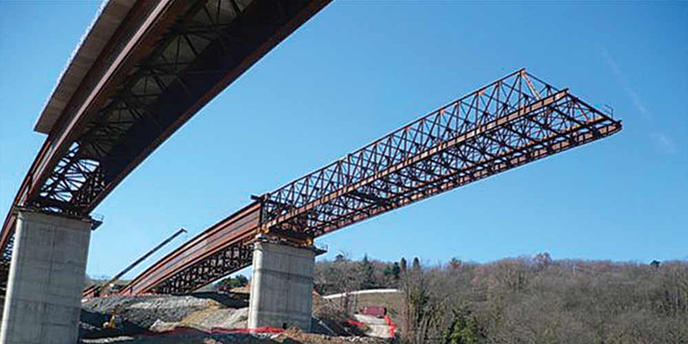
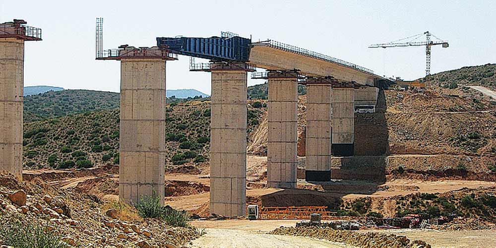
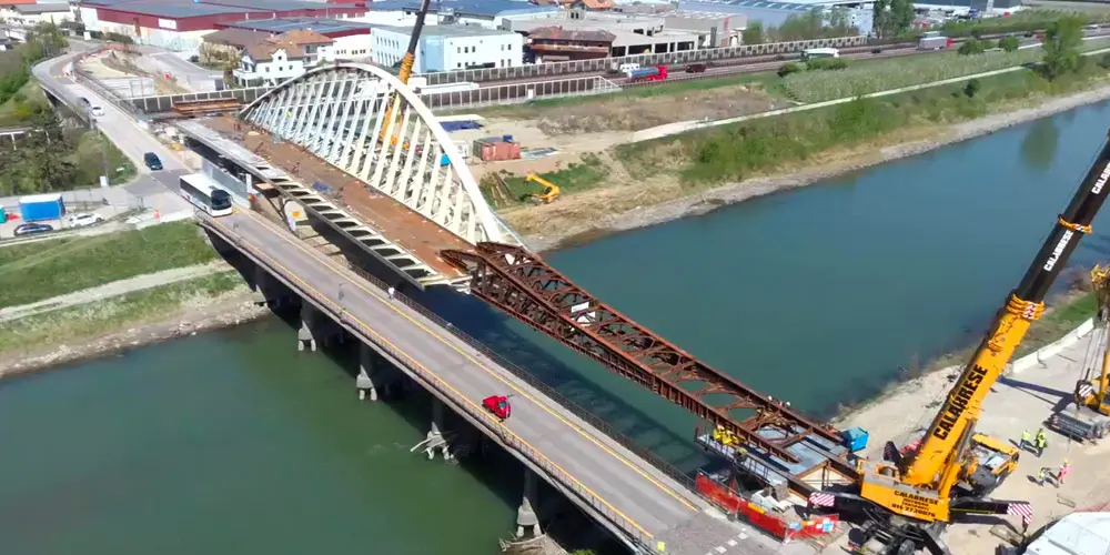
The bridge over the River Adige is composed by a single span of 81.4m with a bowstring arch supporting a 6.5m-wide carriageway, a pedestrian walkway and a cycle path.
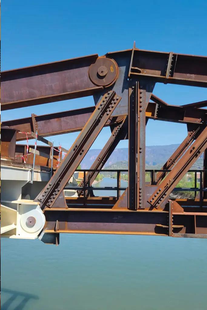
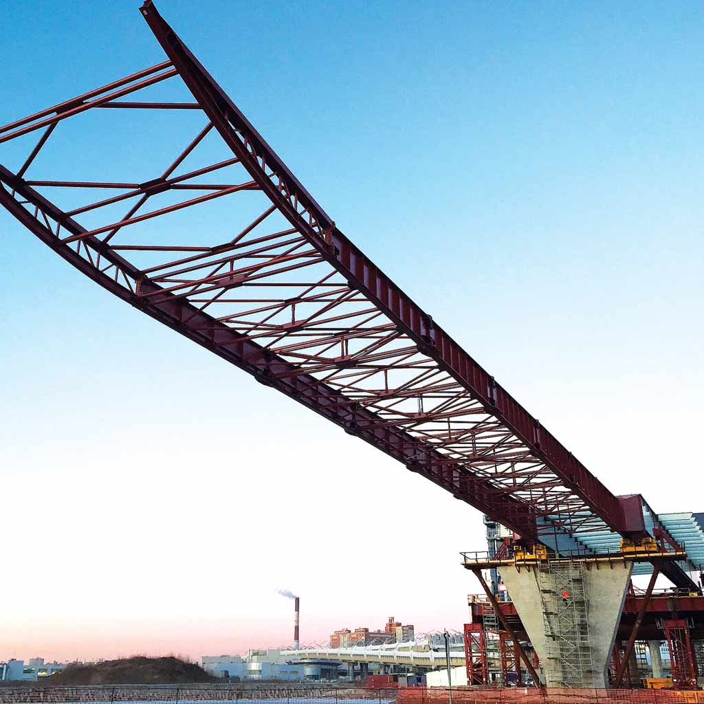
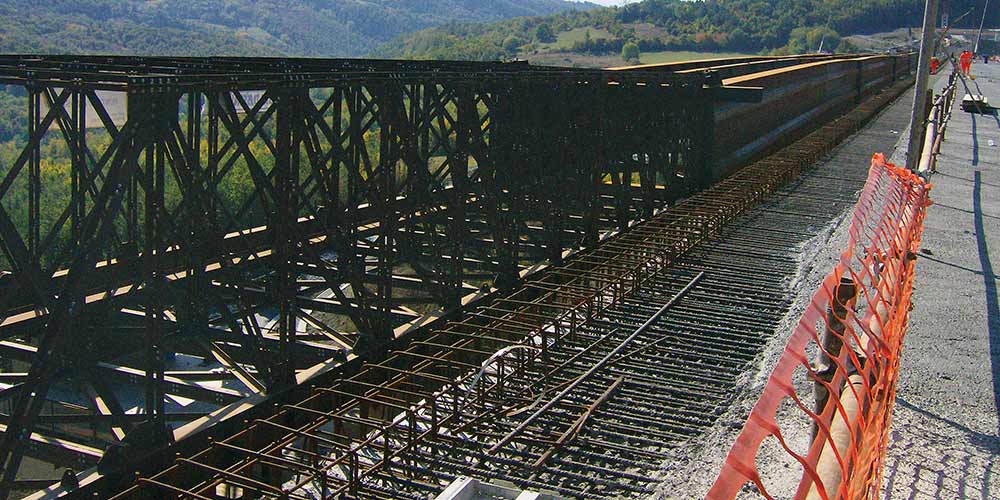
It consists of a straight steel deck with an orthotropic plate, supported by a single steel archinclined at 20° from the vertical and located laterally, in an eccentric position with respect to the longitudinal axis. The arch has an irregular pentagonal box and a jib of 13.5 m from the deck. The arch-bridge connection is made by means of welded I-shaped hangers with variable section.
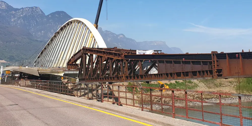
The bridge over the River Adige is composed by a single span of 81.4m with a bowstring arch supporting a 6.5m-wide carriageway, a pedestrian walkway and a cycle path.
It consists of a straight steel deck with an orthotropic plate, supported by a single steel archinclined at 20° from the vertical and located laterally, in an eccentric position with respect to the longitudinal axis. The arch has an irregular pentagonal box and a jib of 13.5 m from the deck. The arch-bridge connection is made by means of welded I-shaped hangers with variable section.
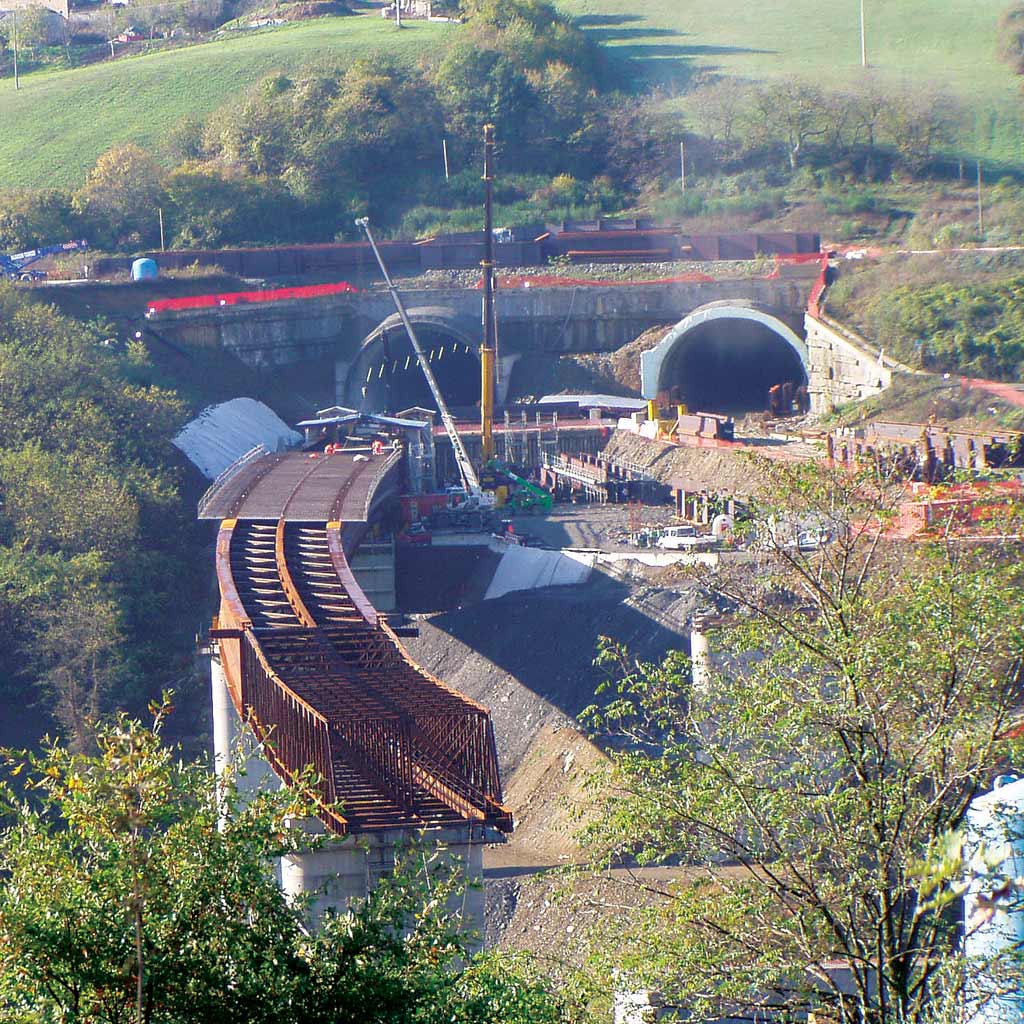
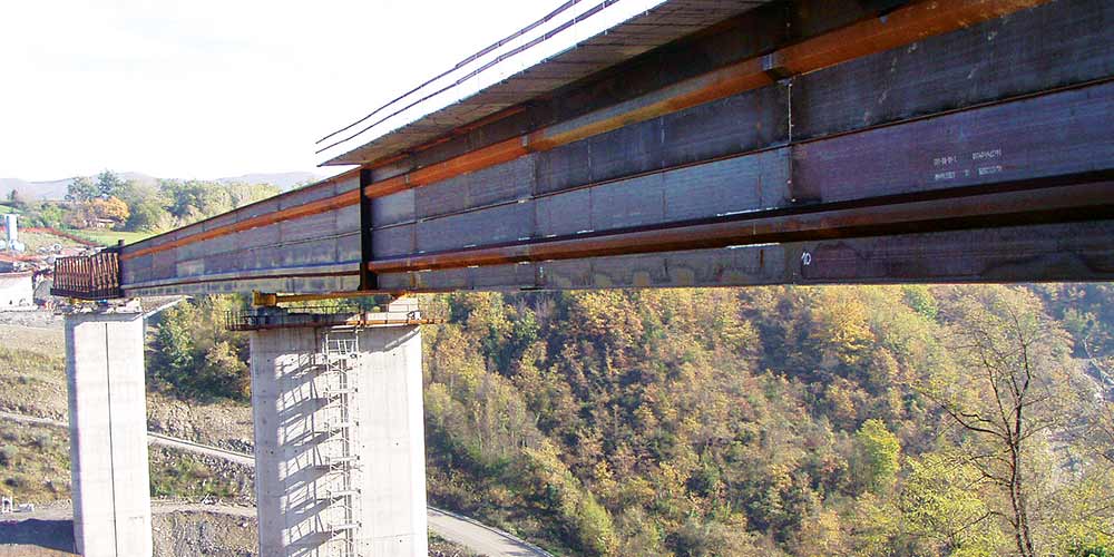
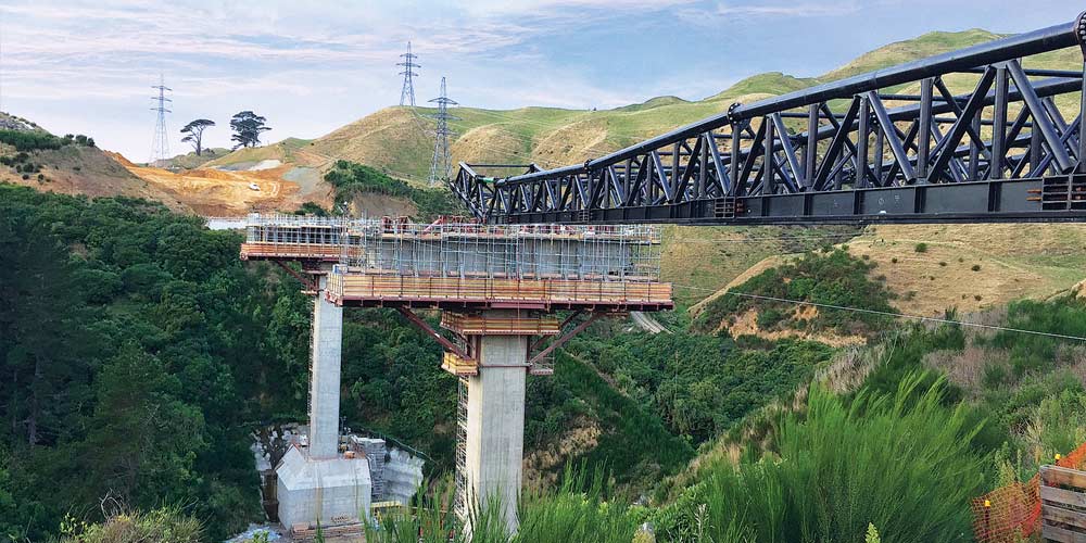
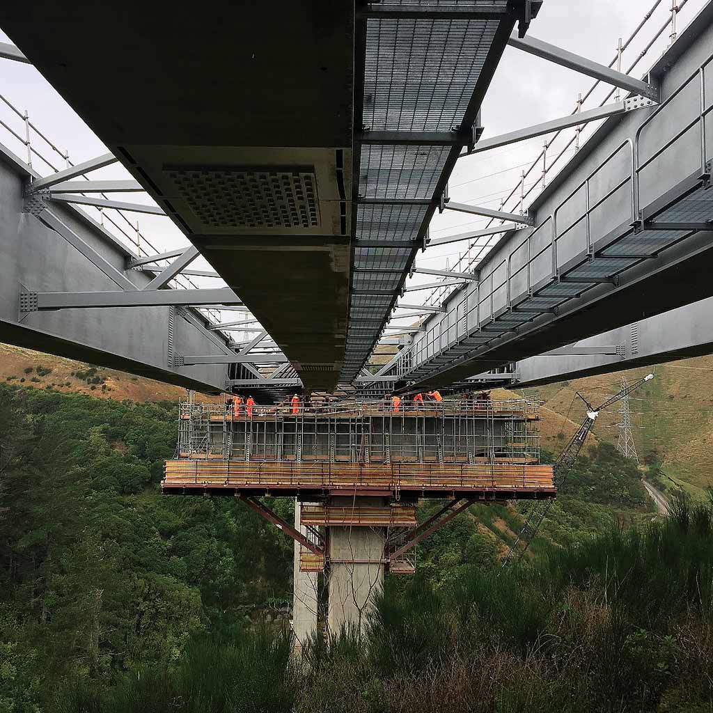
The deck consists of a multi-cellular box with 5 webs and a maximum height of 1.6m with diaphragms spaced by 3.3m. The cycle path and the pedestrian walkway, with an effective width of 2.8m and 2.5m, are supported by I-section cantilevers with variable height and placed in correspondence of the diaphragms. The pedestrian path progressively distances itself from the roadway proceeding towards the centre line.
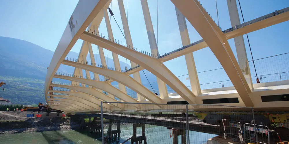
The deck consists of a multi-cellular box with 5 webs and a maximum height of 1.6m with diaphragms spaced by 3.3m. The cycle path and the pedestrian walkway, with an effective width of 2.8m and 2.5m, are supported by I-section cantilevers with variable height and placed in correspondence of the diaphragms. The pedestrian path progressively distances itself from the roadway proceeding towards the centre line.