Carrovaro Nichupte

The Nichupte launching beam

Launching beam project for the assembly of the new “Nichupte Bridge” viaduct.

Category: Special equipment
Services: Detailed Design – Executive Project of Main and secondary structures of the launching beam
Period: December 2022 – ongoing
Client: Deal

Carrovaro Nichupte

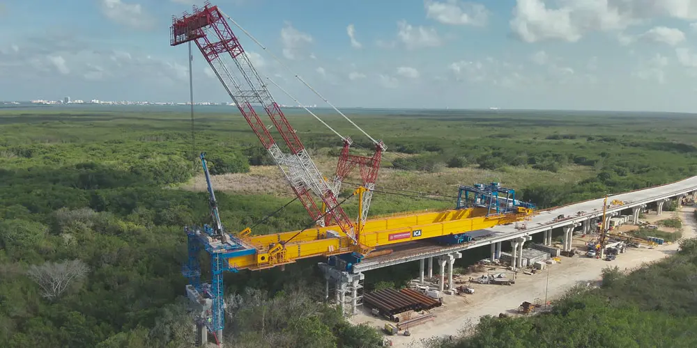
The Nichupte launching beam is a special piece of equipment designed for the assembly of the new “Nichupte Bridge” viaduct located in Cancun, Mexico. The purpose of the structure is to allow the construction of the foundations, the piers and the installation of the deck, composed of prefabricated concrete beams, without carrying out any construction site installation in the entire area of intervention of the equipment.

The machine is operational for the part of the viaduct between pier 40 and pier 60 (20 spans of approximately 35m), an area which, due to the presence of the lagoon below, does not provide for the possibility of construction site installations for environmental reasons.
The launching beam is made up of two single-cell caissons of 96m in length. The boxes have an almost constant height of 3.22 m; only the first rear ashlar has a height of 2.82 m. There are ribbed slabs along the entire length both longitudinally and transversely. The diaphragms are placed with a constant pitch of approximately 3.8m.

Carrovaro Nichupte
Carrovaro Nichupte

The machine is operational for the part of the viaduct between pier 40 and pier 60 (20 spans of approximately 35m), an area which, due to the presence of the lagoon below, does not provide for the possibility of construction site installations for environmental reasons.
The launching beam is made up of two single-cell caissons of 96m in length. The boxes have an almost constant height of 3.22 m; only the first rear ashlar has a height of 2.82 m. There are ribbed slabs along the entire length both longitudinally and transversely. The diaphragms are placed with a constant pitch of approximately 3.8m.
Carrovaro Nichupte

The main beams are connected transversely by n. 3 box-shaped crosspieces, one at the rear, one at two thirds of the span and one at the front.
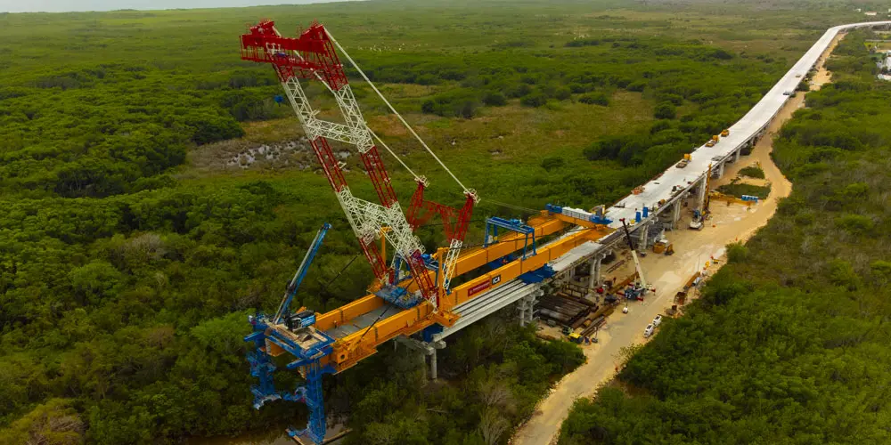
The machine has a cable-staying system made up of 4 stays anchored at the top of the end crosspieces and at the top of the pylon located in correspondence with the central crosspiece.

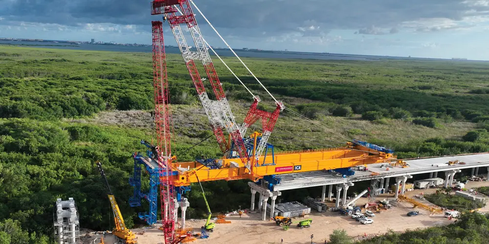
The structure is completed by the two platforms, a rear one which houses the generators and guarantees access to the entire rear part (main access to the machine and inspection of the containers), and a front one where all the construction site activities are carried out. The various work levels are connected to each other via external walkways and stairs.
The overall size outside the wagon is 101×25.7×17.4m
Carrovaro Nichupte
Carrovaro Nichupte

The structure is completed by the two platforms, a rear one which houses the generators and guarantees access to the entire rear part (main access to the machine and inspection of the containers), and a front one where all the construction site activities are carried out. The various work levels are connected to each other via external walkways and stairs.
The overall size outside the wagon is 101×25.7×17.4m

Carrovaro Nichupte
Torri Eur

Torri Eur

Restoration and conservative rehabilitation of the “Torri Eur” real estate complex.

Category: Civil buildings
Services: Final design
Period: April 2021 – ongoing
Client: MBM S.p.A.

The EUR towers complex is made up of a group of several buildings which, having considerable architectural and urban planning importance, were once redeveloped and transformed into Telecom’s headquarters.
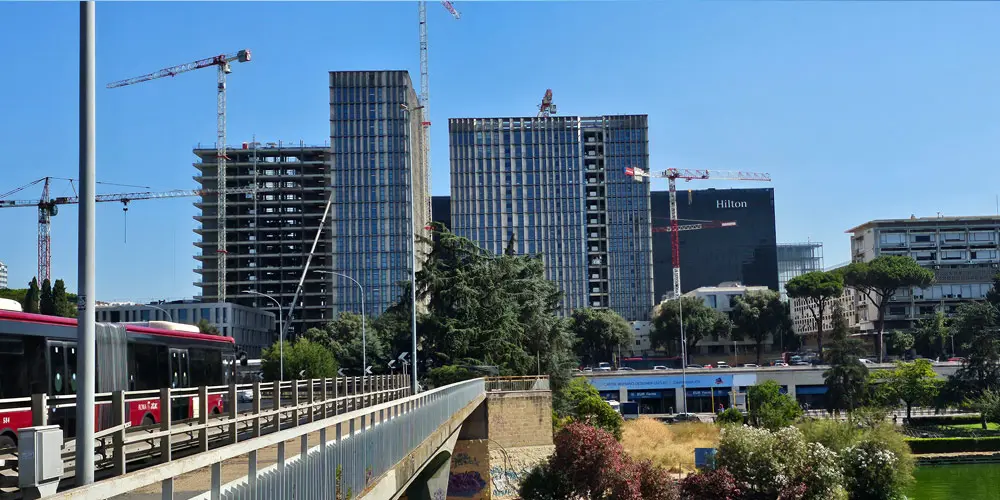
The intervention lot, located in the municipality of Rome, on the northern side of the EUR artificial lake and close to the EUR Fermi metro station, has dimensions in plan of approximately 154 m x 100 m, and a surface area of over 15,500 m2.

The structural project handled by Steel Project Engineering is part of a larger restoration and conservative rehabilitation intervention, in order to achieve seismic and static adaptation to current regulations, while remaining faithful to the original project with interventions targeted on critical structural elements. Our studio, specifically, dealt with the executive and construction project for all aspects concerning the metal structures (for a total of approximately 6,000 tons) and the interfaces with the existing reinforced concrete structures.

The structural project handled by Steel Project Engineering is part of a larger restoration and conservative rehabilitation intervention, in order to achieve seismic and static adaptation to current regulations, while remaining faithful to the original project with interventions targeted on critical structural elements. Our studio, specifically, dealt with the executive and construction project for all aspects concerning the metal structures (for a total of approximately 6,000 tons) and the interfaces with the existing reinforced concrete structures.

The complex consists of five existing buildings, described below:

• Three tower buildings (B, C, C1) whose load-bearing framework is made of reinforced concrete made up of single walls and beams cast on site, generally in slab thickness, measuring approximately 48.50 m x 14.00 m (C and C1) and 38.60m x 27.70m (B);
• A building with a quadrangular plan (A), in reinforced concrete consisting of a frame system, measuring approximately 42.50 m x 42.50 m;
• A building with an elongated plan, two underground floors and four floors above ground (D), in reinforced concrete consisting of a frame system, measuring approximately 14.00 m x 99.00 m.
There are also a series of newly built metal carpentry buildings that fit between the buildings previously described, connecting them to each other:
• Buildings G1, G2, G3, G4, G5, two floors;
• Building E, four floors. This, being the central building, has the role of the central nucleus (represents the hub of the entire complex) and therefore has an irregular shape, having to be inserted between the existing surrounding blocks.

PEX – Parc Des Expositions

PEX – Parc Des Expositions

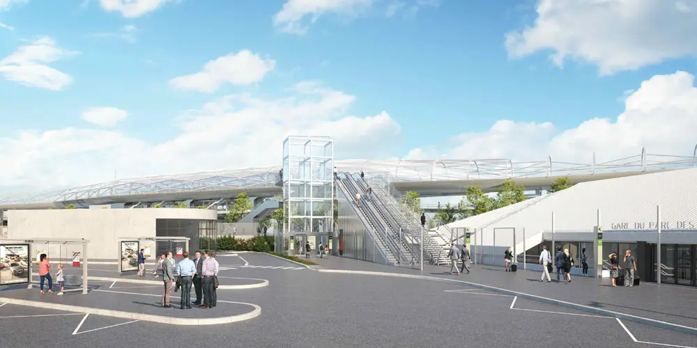
Executive design of the Gare du Parc Des Expositions (PEX) and the Passerelle.

Category: Civil buildings
Services: Final design
Period: June 2022 – ongoing
Client: Cimolai S.p.a.

PEX – Parc Des Expositions

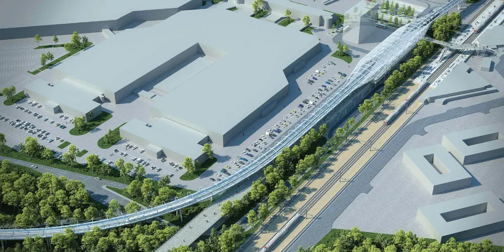
The development operation of the Grand Paris Express public transport network extends over a length of approximately 20 km. It has two underground sections, north (sector 3) and south (sector 1), and one aerial section (sector 2). The aerial section extends for approximately 5.2 km between Gonesse and Tremblay-en-France.
We took care of the executive design of the “Gare du Parc des Expositions” (PEX) and the “Passerelle” which are part of the complex of the elevated section. The station is crossed by the viaduct on which trains circulate and whose structures are independent from those of the remaining structures. The station structure extends over a width of approximately 28 meters (overall) and a length of approximately 181 m (without expansion joints), on 4 levels:
– on the ground floor, technical rooms and a circulation space for the exhibition centre;
– in the basement, circulation spaces and spaces reserved for operator personnel;
– on the mezzanine floor, a public space for the circulation of passengers;
– on the upper level and on a central part 54 m long, the platforms.

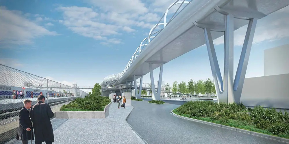
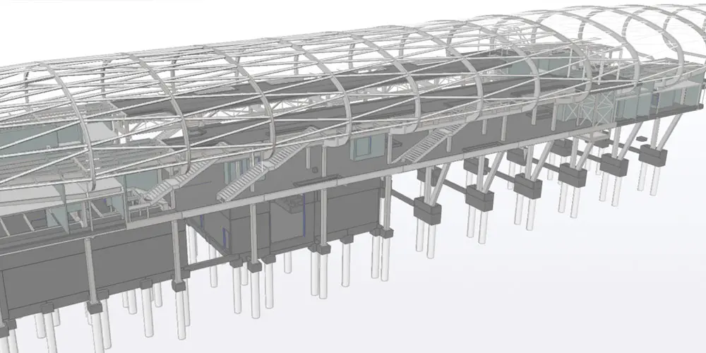
On the ground floor, the main structure consists of steel frames made up of straight columns and V-shaped columns approximately 8.50 m high. The columns are connected at the top by a welded composite beam with a double T section. On the mezzanine floor there are independent double portals, made up of straight box-section steel uprights, fitted at the top to compose a Vierendeel scheme.
The roof connects at the level of the platforms and is made up of a series of arches arranged at 9 m intervals, connected by tubular section purlins that support the EFTE roof. The mezzanine floor is made up of a composite steel-concrete sectional floor; on the platform level there is, however, a solid slab in approx.

PEX – Parc Des Expositions

The “Passerelle” allows you to connect the “Paris Nord 2” commercial area to the north-west and the “Parc International Des Expositions de Paris-Nord Villepinte (PIEX)” to the south-east. It allows crossing the RER tracks and connecting to the future PEX station. The primary horizontal structure consists of a main central beam, continuous across the entire walkway. The typical retaining cross section is a welded composite trapezoidal box, with a width varying from 800 mm to 1200 mm and an overall height of 660 mm. The caisson is widened to span the wide span in the station extension. The T-section or double-T section oars with variable inertia (T-profiles: variable height from 50 to 200mm, double-T profiles: variable height from 700 to 250mm) are grafted onto the central beam and support the orthotropic slab covered with a finish on asphalt. The oars are arranged at an average distance of approximately 2.55m. A series of columns, composed of round tube profiles (D=193.7mm external), act as support for the walkway deck. There are also stairs, support structures for elevators and escalators.

DEA San Giovanni

DEA San Giovanni

Final Design of the “San Giovanni di Dio” hospital complex.

Category: Civil buildings
Services: Final design
Period: May 2023 – ongoing
Client: USL Toscana Centro

DEA San Giovanni

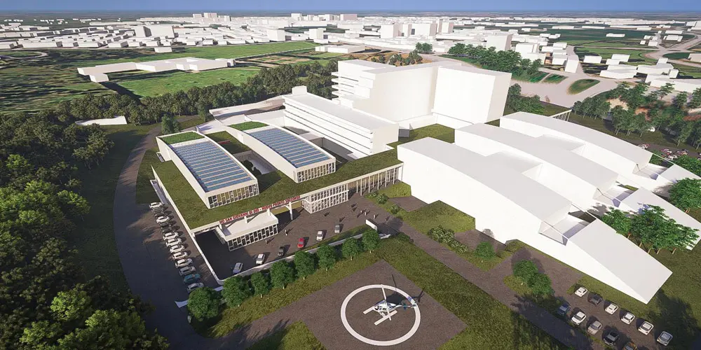
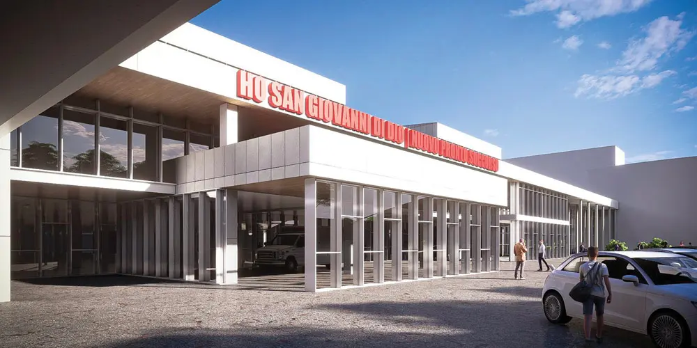
The new emergency room structure of San Giovanni di Dio in Florence will be made of reinforced concrete, and will have plan dimensions of 85m x 53m, and a height of 20m. It is composed of a basement level, with dimensions of 2000 m2, and 3 levels above ground, respectively of 4285 m2 (ground floor and first floor), 3900 m2 (second floor). The third level has a part covered by a metal structure with concentric braces, for a total surface area of 2200m2. The decks will be made using a solid concrete slab in order to allow the correct installation of the hanging systems. The horizontal actions will be assigned mainly to the stair-lift blocks and the reinforced concrete partitions arranged ad hoc in the plan so as not to compromise either the aesthetic or functional aspect. Since the site where the emergency room will be built appears to have a non-excessive design seismic action, a NON-dissipative design was opted for.

Moving Walkway

Moving Walkway

Pedestrian connection system between the Erzelli-Fs station and Cristoforo Colombo airport, called "Moving Walkway".

Category: Pedestrian bridges
Services: Technical and Economic Feasibility Design
Period: June 2024 – July 2024
Client: Municipality of Genoa
Value: € 20’000’000.00 (S.04)

Moving Walkway

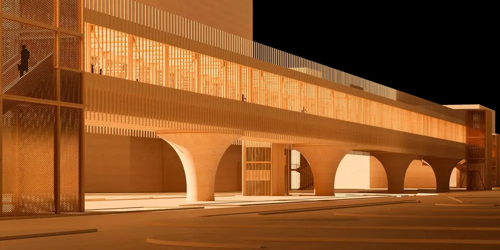
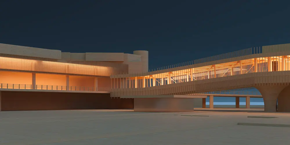
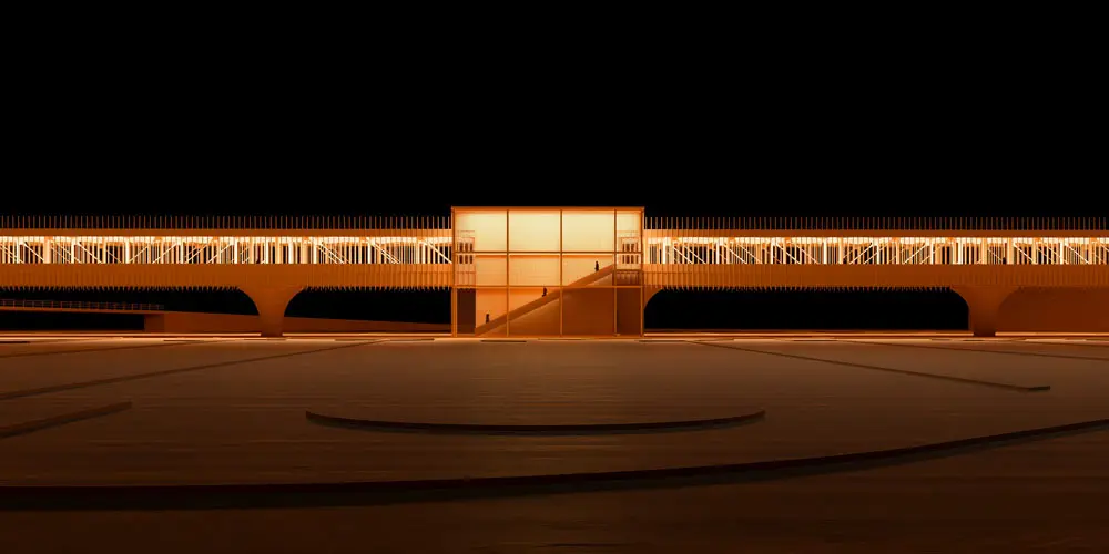
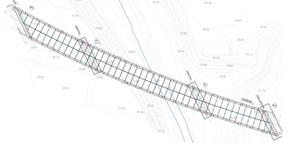
The Moving Walkway is the connection system between the Cristoforo Colombo Airport of Genoa and the future Erzelli-Airport railway station: an elevated connection that allows you to reach the airport terminal with direct access to the airport terminal. It features a development track of about 640 meters, entirely on a viaduct, with a typical span of 42.5 meters and a height from the ground of about 6 meters, not interfering with existing roads and infrastructures.
The main objective during the design phase was to ensure optimization of the project based on the competition. The optimization of the main and secondary structures aimed to reduce the weight of the metal frameworks and improve the geometries of the scaffolding, harmonizing the architectural hypotheses with functional and aesthetic needs.

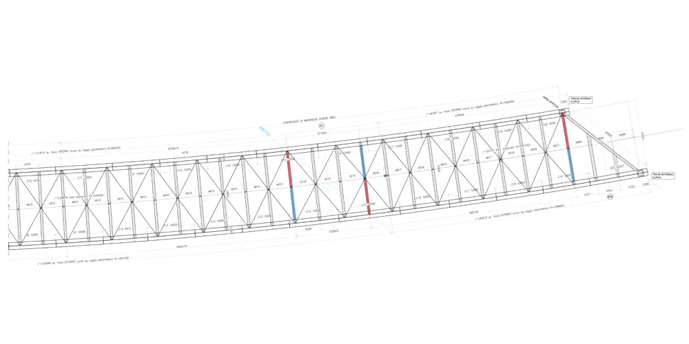
For the elevated path of the Moving Walkway, a Mohniè beam scheme was chosen for the load-bearing walls, as it is more efficient in terms of structural weight. This type combines architectural lightness and reduction of structural bulk, improving the usable surface and reducing the aesthetic impact.
For the braces of the truss beams, round tubular profiles were proposed to maintain aesthetics, and possible optimization of the lower brace with double T profiles.
For the lower decking members, the use of open-rolled profiles was proposed, also to simplify the installation of the corrugated sheet. For the substructures, a single support for each wall was proposed to reduce maintenance costs and simplify assembly. The structural calculation will use modern tools and BIM modeling to achieve maximum exploitation of the members while respecting regulatory safety levels.
The structural engineering also considered aspects of fabrication, assembly, and lifting to prevent issues during the structure assembly phases.

Moving Walkway
Moving Walkway

For the elevated path of the Moving Walkway, a Mohniè beam scheme was chosen for the load-bearing walls, as it is more efficient in terms of structural weight. This type combines architectural lightness and reduction of structural bulk, improving the usable surface and reducing the aesthetic impact.
For the braces of the truss beams, round tubular profiles were proposed to maintain aesthetics, and possible optimization of the lower brace with double T profiles.
For the lower decking members, the use of open-rolled profiles was proposed, also to simplify the installation of the corrugated sheet. For the substructures, a single support for each wall was proposed to reduce maintenance costs and simplify assembly. The structural calculation will use modern tools and BIM modeling to achieve maximum exploitation of the members while respecting regulatory safety levels.
The structural engineering also considered aspects of fabrication, assembly, and lifting to prevent issues during the structure assembly phases.

Viadotto Rabbi

Rabbi viaduct

Project for the launch of the bridge.

Category: Road bridges
Services: Executive design
Period: July 2021 – August 2022
Client: IDRO.STRADE S.r.l

Viadotto Rabbi

The viaduct over the Rabbi river is included in the section Km 1+930.59 and Km 2+141.67 of the new ring road system of Forlì, connecting the ring road East – Lot 3.
The work consists of a bridge over 3 spans of spans equal to 58.58, 94.30 and 58.20 m; it houses a road platform with a constant width of 10.5 m and two side curbs, on which a road safety barrier is mounted, with a width of 0.75 m; in addition to the curbs, there is a net space of 0.95 m used as a service sidewalk.

The structure consists of a grid of steel beams with two main beams arranged parallel along the development axis of the viaduct and by crosspieces orthogonal to the main beams with a regular pitch of about 5 m on which rests a roadway slab with a thickness equal to 21cm + 6cm of predalles. The two main metal beams have a double T cross section of variable height from 4 m (lowest value recorded in the span) up to 6.00 m (maximum value recorded in axis with the pile).
The bridge has 2 central reinforced concrete piers in which allow the Rabbi River to be crossed with the maximum span and two traditional reinforced concrete abutments.
The foundations of piers and abutments are made using 120 cm diameter piles with a length of 28 m for the abutments and 100 cm diameter piles and 30 m long for the piles.

Viadotto Rabbi
Viadotto Rabbi

The structure consists of a grid of steel beams with two main beams arranged parallel along the development axis of the viaduct and by crosspieces orthogonal to the main beams with a regular pitch of about 5 m on which rests a roadway slab with a thickness equal to 21cm + 6cm of predalles. The two main metal beams have a double T cross section of variable height from 4 m (lowest value recorded in the span) up to 6.00 m (maximum value recorded in axis with the pile).
The bridge has 2 central reinforced concrete piers in which allow the Rabbi River to be crossed with the maximum span and two traditional reinforced concrete abutments.
The foundations of piers and abutments are made using 120 cm diameter piles with a length of 28 m for the abutments and 100 cm diameter piles and 30 m long for the piles.

Viadotto Rabbi
Ponte di Thionville

Thionville bridge

Project of the Thionville Bridge.

Category: Road bridges
Services: Final design
Period: October 2021 – April 2022
Client: Smitu Thionville Fensch

Ponte di Thionville

The main structure has a total length of approximately 309 meters and consists of two separate decks. The first deck “(C0-P2” has a plan layout with a radius of curvature of 50.0m and develops over two spans of 34m + 52 m for a total length of 86 m. The deck “P2-C7” has a rectilinear route over 5 spans (58 + 42 + 39 + 48.5 +34 m) for a length of 222 m.
The platform has a total width of approximately 16m, divided into a central part of 7.00 meters wide for the BHLS, a cycle-pedestrian path 5.00 meters wide and 1 sidewalk 2.45 meters wide.

The 1.89 m high cross section is made by a metal box with four webs. Metal slabs lean on the upper flanges and have the function of permanent formwork for the rounding of a reinforced concrete slab 27 cm thick.
The connection between footings and slab is ensured by rungs. The reinforced concrete slabs located on the overhangs are made by prefabricated semi-slabs with concreting completely on site. The overhangs are supported by variable-height steel brackets located in correspondence of the standard struts and bridge parts.

The overall weight is approximately 2000 tonnes, of which 600 relate to the curved section alone.
Two laminated elastomer bearings are located on all the piers or abutments; the C0-P2 deck in correspondence of the alignments P2 and C0 on the curved internal side, has special anti-lifting bearings.

Ponte di Thionville
Ponte di Thionville
Ponte di Rouen

Rouen bridges

Executive design and assembly of steel bridges.

Category: Road bridges
Services: Executive design
Period: March 2021 – July 2022
Client: BIT S.p.a.

Ponte di Rouen

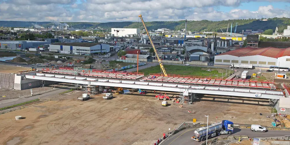
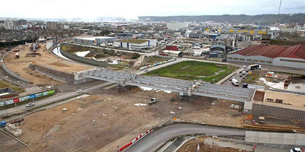
The works include the creation of approximately 1.1 km of expressway between the Stalingrad interchange of the current South III expressway and the left bank access viaduct to the Flaubert bridge.

Ponte di Rouen

The works include the creation of approximately 1.1 km of expressway between the Stalingrad interchange of the current South III expressway and the left bank access viaduct to the Flaubert bridge.

This new portion notably includes three reinforced soil embankments and two engineering structures, including a railway crossing.
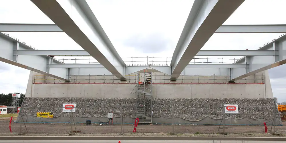
The Madagascar structure consists of two separate decks: the east deck is 13.50 m wide and the west deck is 12.68 m wide. The total length is 116 m over 3 spans 36 m + 44 m + 36 m.

Ponte di Rouen
Ponte di Rouen

This new portion notably includes three reinforced soil embankments and two engineering structures, including a railway crossing.
The Madagascar structure consists of two separate decks: the east deck is 13.50 m wide and the west deck is 12.68 m wide. The total length is 116 m over 3 spans 36 m + 44 m + 36 m.

Ponte di Rouen

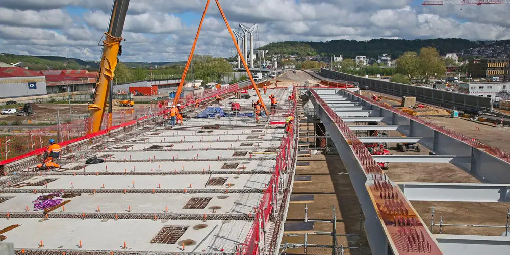
The layout is partly straight and partly curved; the longitudinal profile is a ramp with a constant slope. Each deck is made up of 2 metal beams 1.70 m high; the metal beams are reconstituted welded profiles.
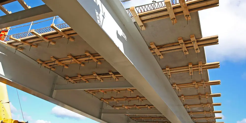
The beams are connected to a fully prefabricated reinforced concrete slab 30 cm thick. Each beam rests on a laminated elastomer bearing. Four of the metal spacers are used.

Common type except C5-C6, C11 and C12, C5-C6, C11 and C12 type (before and after pier spacers), pier type and abutment type. The framework of the deck will be assembled on site and then moved by SPMT and, finally, set up by crane using pairs of cranes. Once the deck has been placed on temporary supports, the prefabricated slabs will be put in place. The deck will be completed by concreting the keying strips and completely deck finishes and equipment.

Ponte di Rouen
Ponte di Rouen

Common type except C5-C6, C11 and C12, C5-C6, C11 and C12 type (before and after pier spacers), pier type and abutment type. The framework of the deck will be assembled on site and then moved by SPMT and, finally, set up by crane using pairs of cranes. Once the deck has been placed on temporary supports, the prefabricated slabs will be put in place. The deck will be completed by concreting the keying strips and completely deck finishes and equipment.

CERN - The “Science Gateway”

CERN – The “Science Gateway”

Assembly project of steel structures.

Category: Erections
Services: Executive Design
Period: February 2021 – February 2022
Client: Cimolai S.p.A.

CERN - The “Science Gateway”

CERN in Geneva: the “Science Gateway”, a structure completely dedicated to education and the dissemination of science. The architecture of Science Gateway, designed by the Renzo Piano Building Workshop design studio, is inspired by the technical installations and underground tunnels of CERN.

The project is located within the area of the European Nuclear Research Center and involves the use of approximately 1600t of metal structural work.
Steel Project Engineering specifically dealt with the study of the executive assembly phases of the 3 pavilions, the 2 tubular structures in metal carpentry and the connecting bridge. The construction site aspect was also taken care of, with the relative organization of the construction site areas.

CERN - The “Science Gateway”

Furthermore, the construction site aspect was taken care of, with the related organization of the construction site areas: this aspect proved to be particularly delicate because of the presence of numerous interfering processes and the consequent evolution of the available areas.
The pavilions, which host exhibitions, practical workshops, shops, restaurants, and also an auditorium, have plan dimensions of 45mx30m (pavilion 1) and 35mx30m (pavilions 2 and 3) and have a structure.
Tubolar structures are two substantially identical structures, which extend over a length of 85m and a width of 10m.

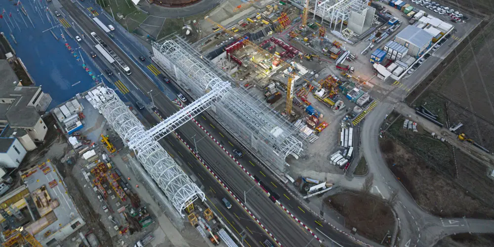
The elevated walkway, which rises over 6m above the ground, in addition to allowing the crossing of the tram line, guarantees the connection between the various buildings.
The construction site area was carefully studied during the various phases of the construction site’s life: the storage and assembly areas, the internal construction site roads, the areas dedicated to lifting machinery were always determined taking into account and safeguarding regular activity of the other processes that took place in the surrounding areas.

CERN - The “Science Gateway”

Assembly began with the installation of the tubular structures and the section of walkway between them. We then moved on to assembling the pavilions and then completing the connecting walkway, paying particular attention to the static scheme which included half-joint. The sections of walkway above the pavilions were positioned at the same time as the pavilions themselves in light of the interference otherwise present with the roofs. In any case, maximum prefabrication was favored and, compatibly with the capacities of the construction site cranes, the bridge frames, the walkway macro segments and some pavilion frames were pre-assembled on the ground and then raised to heights.
We have also designed the various assembly equipment such as temporary piles, eyebolts and lifting frames, temporary supports etc.

Parco Materie Prime

Raw materials park

Erection design of steel structures.

Category: Erections
Services: Erection Design
Period: February 2021 – February 2022
Client: Fincantieri Infrastructure S.p.A.

Parco Materie Prime

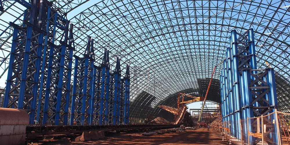
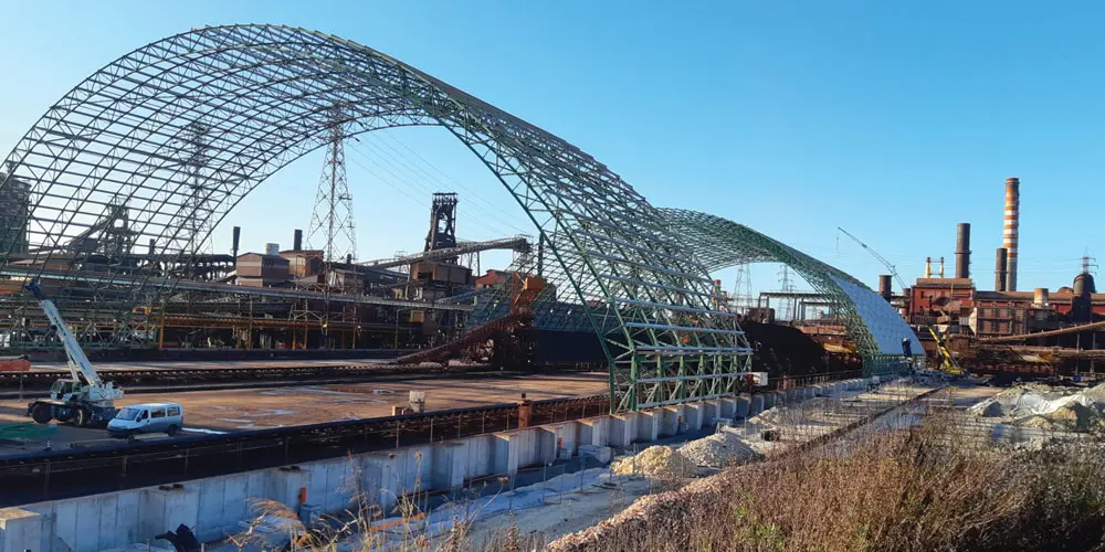
The safe confinement steel structure for the OMO (raw materials) park located inside the “Acciaierie d’Italia” factory in Taranto has plan dimensions of 110 x 385m and is made up of 63 trussed arches, spaced by 6.20 m and with a maximum height of approximately 42m.
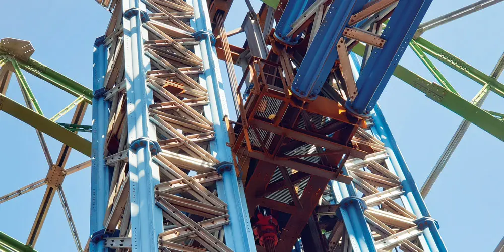
Because of the erection phases, the structure was divided into 9 macro-modules, each consisting of 7 arches. Once the central segments of each macro-module are assembled, they are raised by means of 4 strand jacks connected to a horizontal truss beam which can slide between vertical guides placed on the lifting towers.

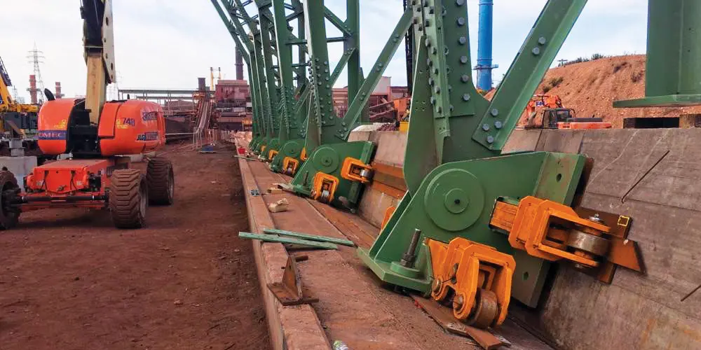
Once the assembly of a single macro-module was completed, it was placed on trolleys and then pushed towards its final position by means of a couple of strand jacks.

Parco Materie Prime
Parco Materie Prime

Once the assembly of a single macro-module was completed, it was placed on trolleys and then pushed towards its final position by means of a couple of strand jacks.

Parco Materie Prime