Projet de montage du nouveau pont sur la rivière Magra.
Category: Road bridges
Services: Erection Design
Period: October 2021 – February 2022
Client: Fincantieri Infrastructure S.p.A.
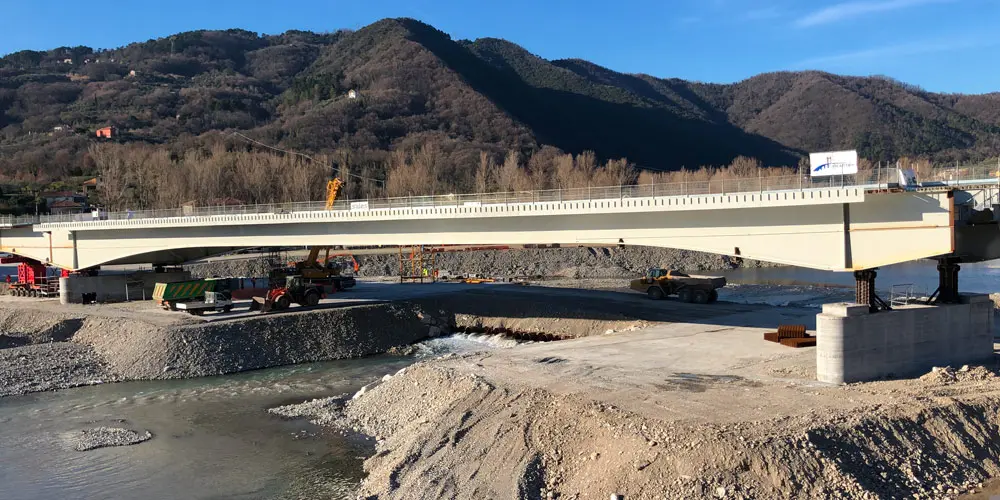
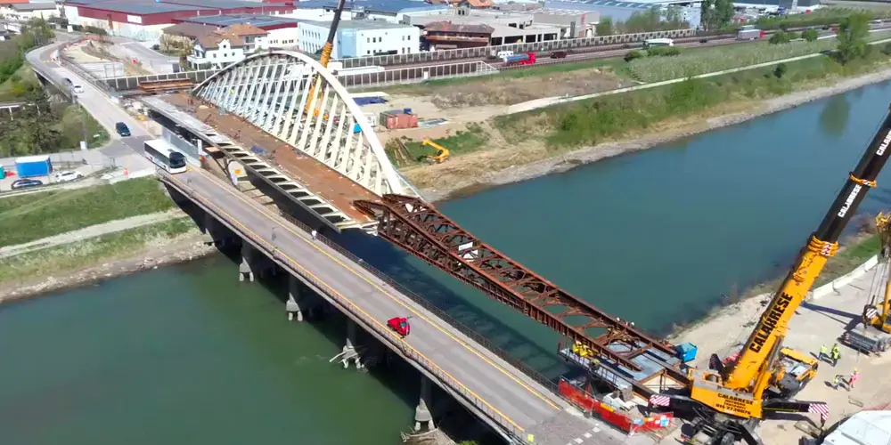
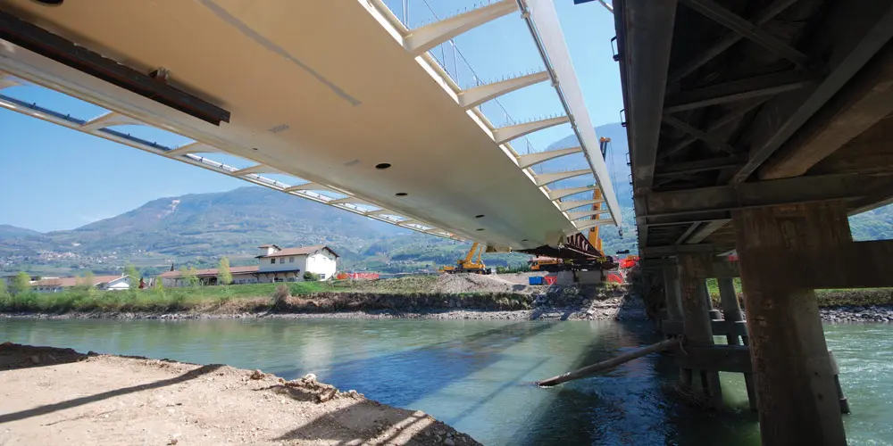
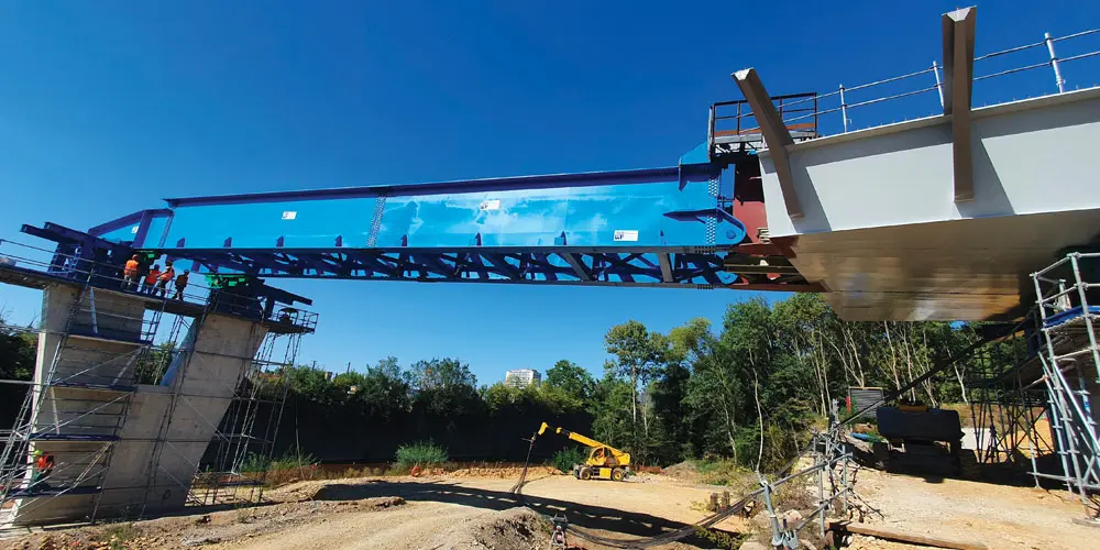
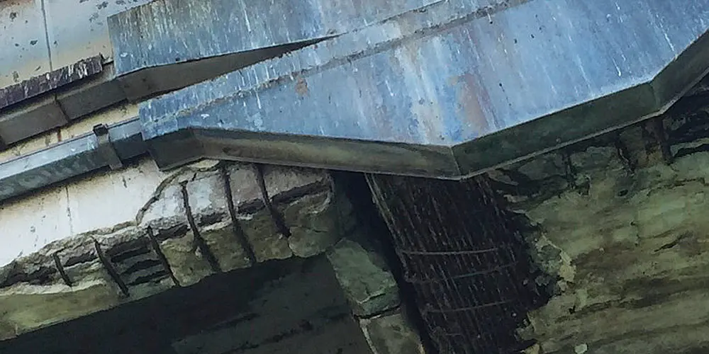
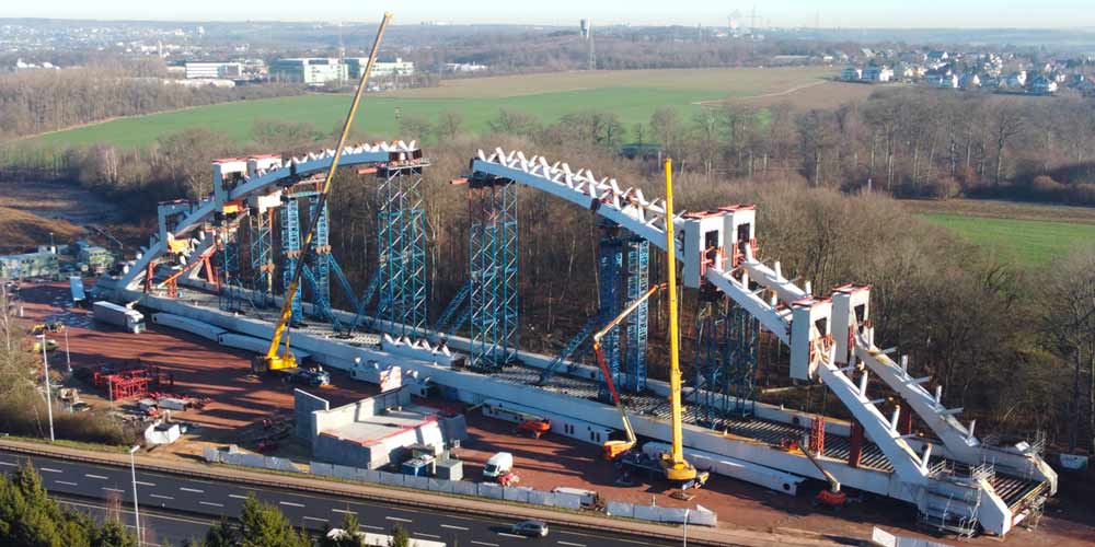
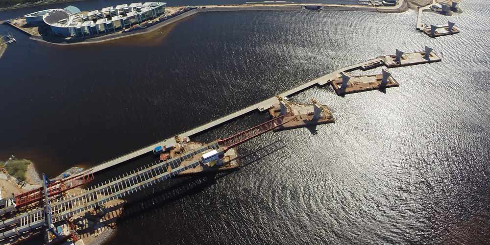
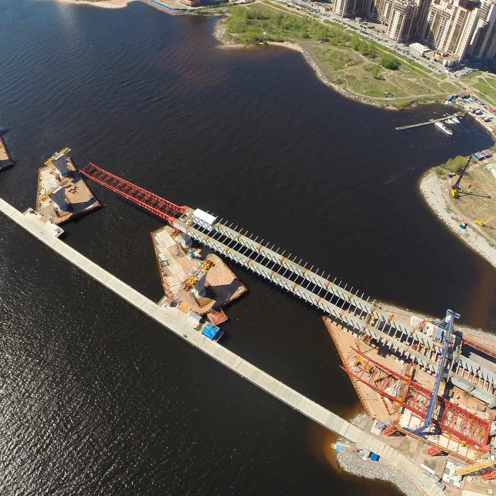
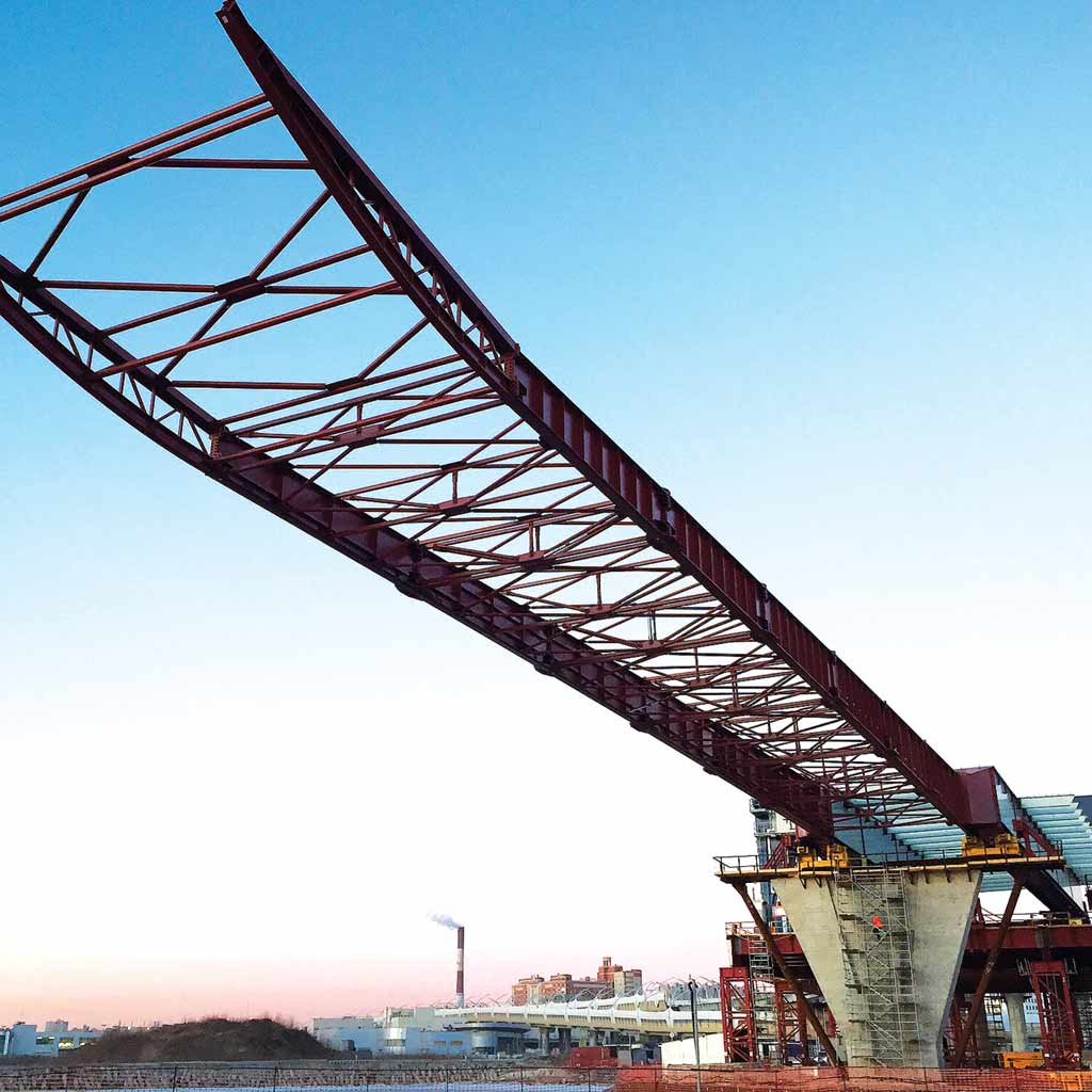
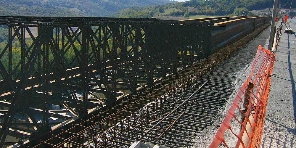
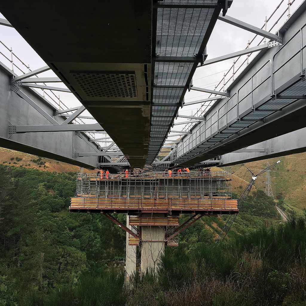
The bridge over the river Magra at Km 10 + 422, needed to be rebuilt after the collapse of the existing bridge. It is made with a girder deck in a mixed steel-concrete system and with a static scheme of continuous beam on 4 spans 57.00 + 2 x 90.00 + 54.00 m, for a total length of 291 m.
The bridge over the river Magra at Km 10 + 422, needed to be rebuilt after the collapse of the existing bridge. It is made with a girder deck in a mixed steel-concrete system and with a static scheme of continuous beam on 4 spans 57.00 + 2 x 90.00 + 54.00 m, for a total length of 291 m.
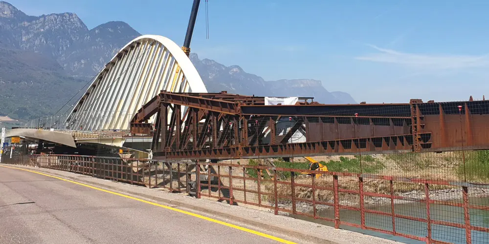
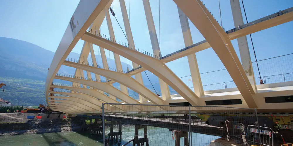
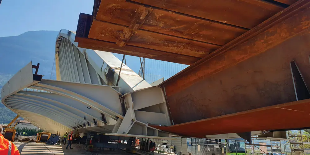
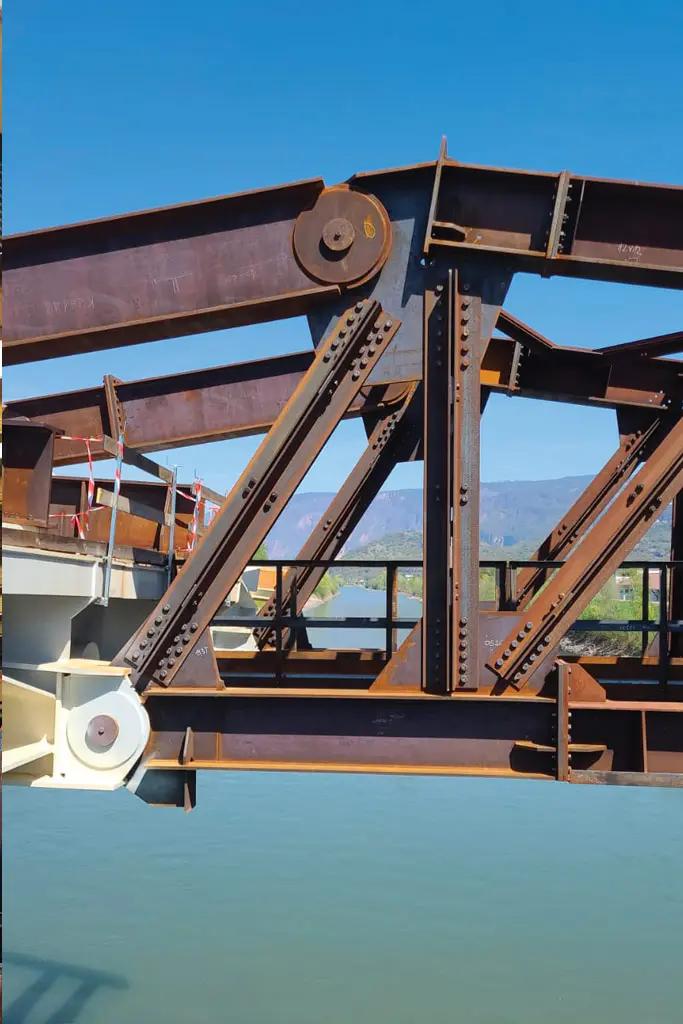
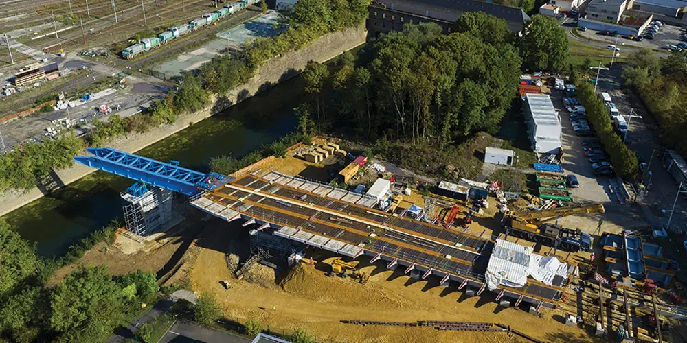
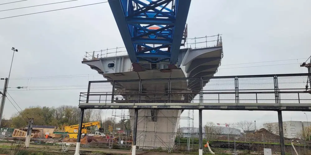
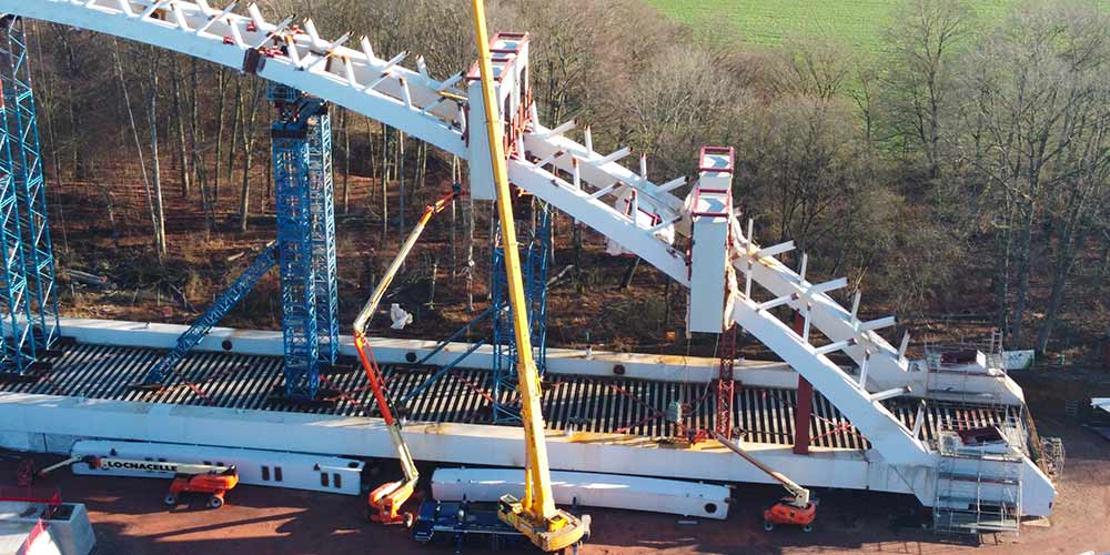
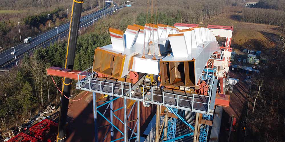
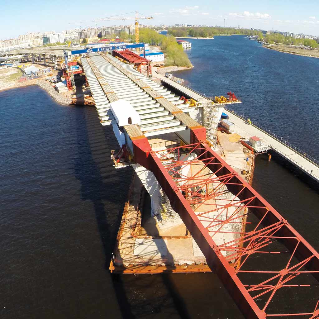
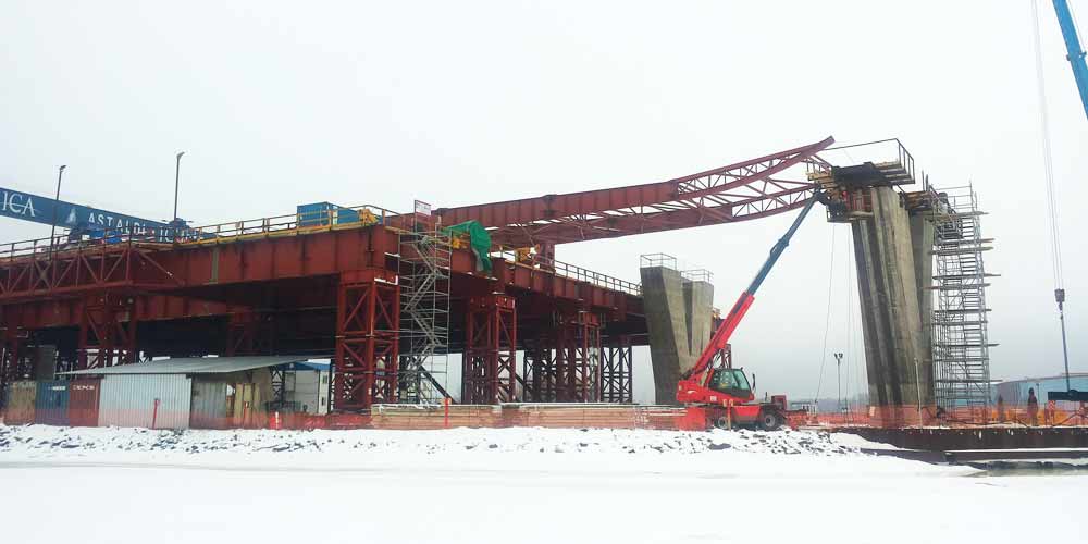
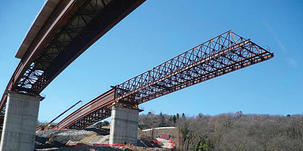
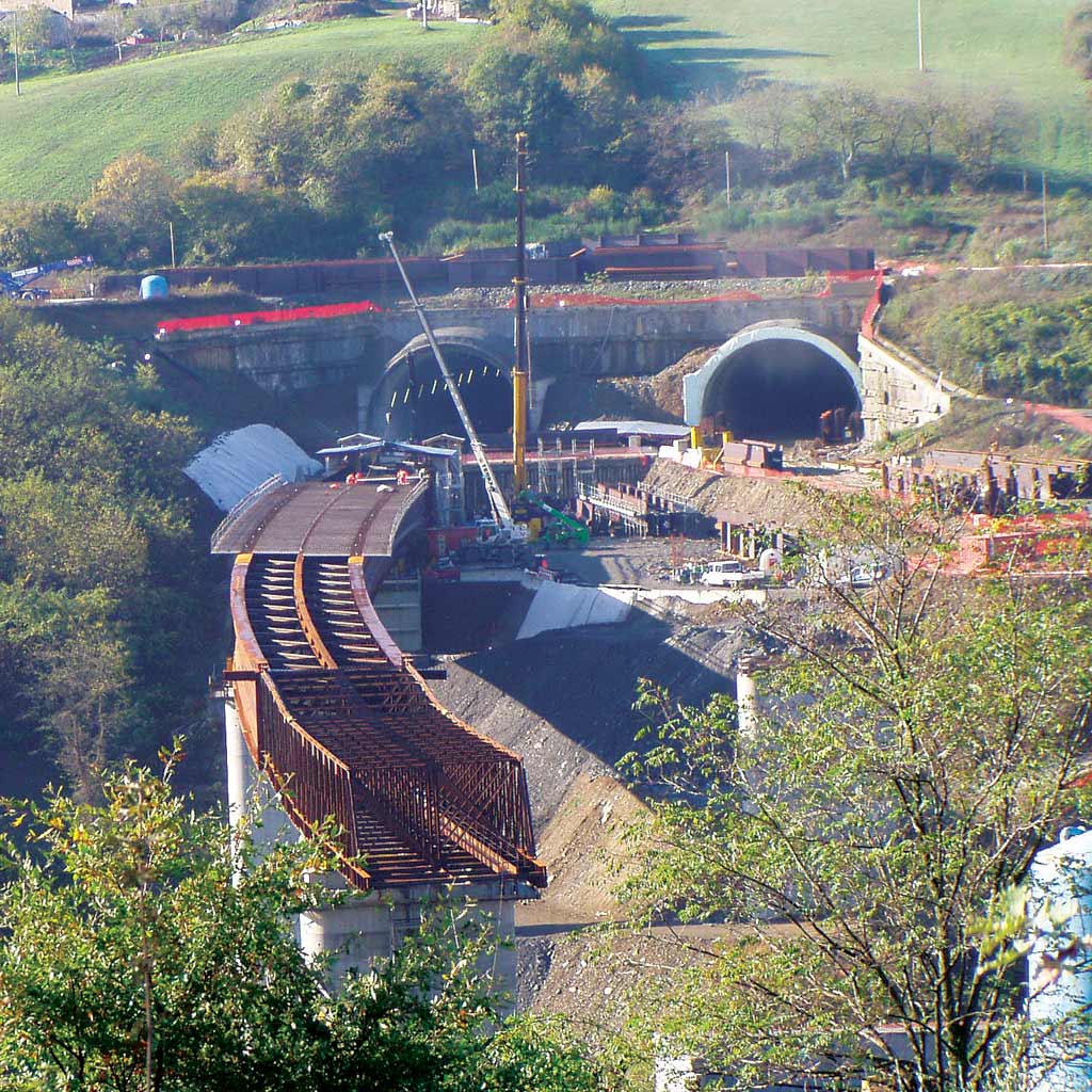
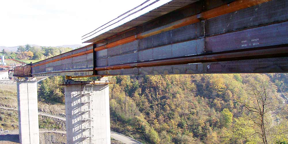
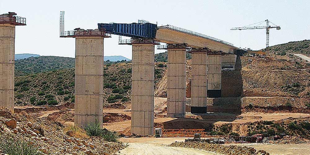
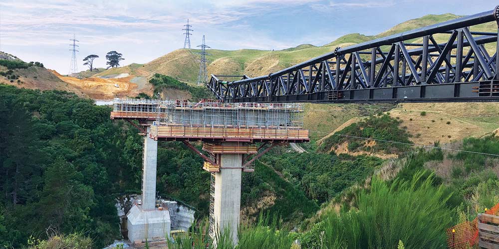
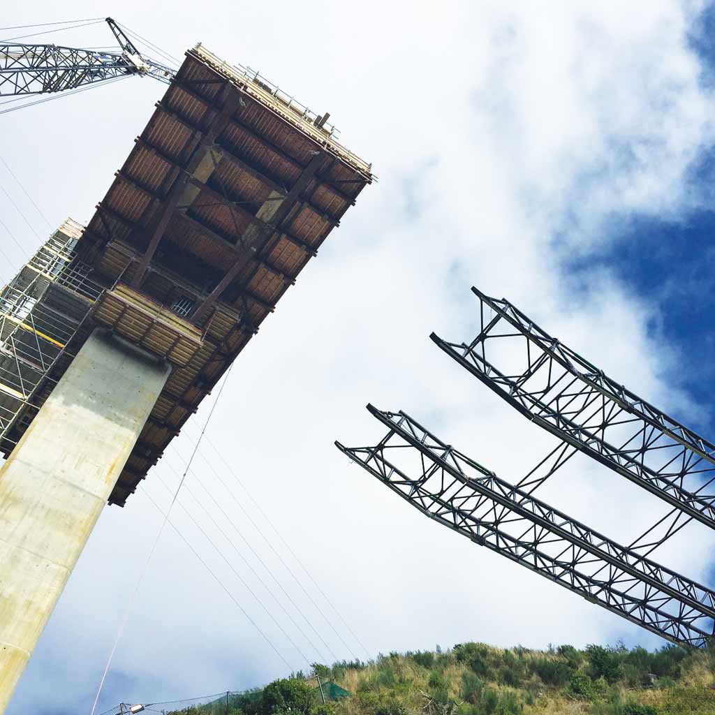
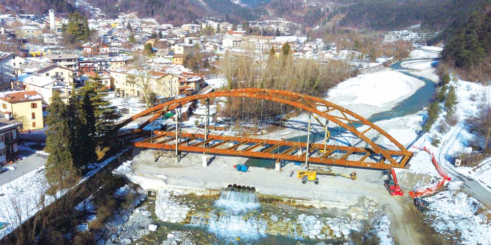
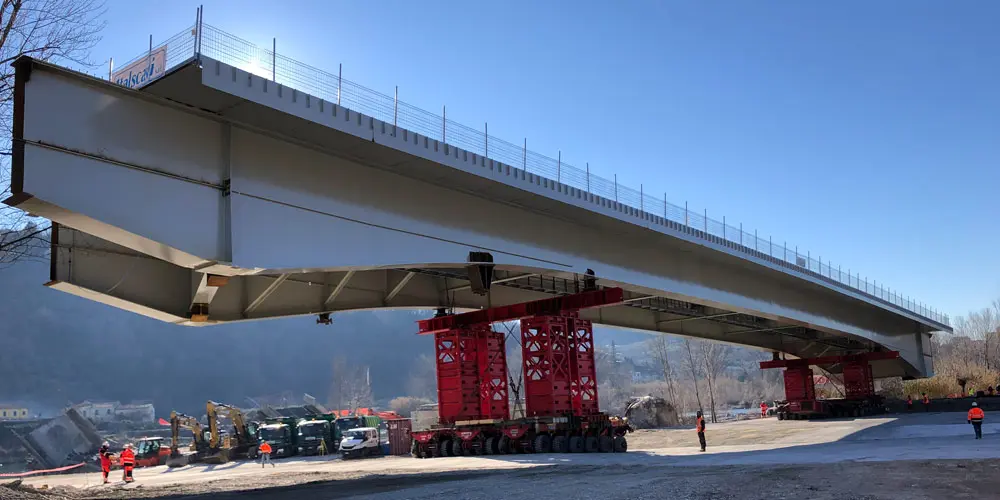
The steel structure was divided into four macro-segments, entirely assembled at the construction site on the river bank by welding the elementary segments. Each of them was then hoisted up on provisional support and transported to their final location by SPTM, after being positioned at height on provisional supports that were also transported.
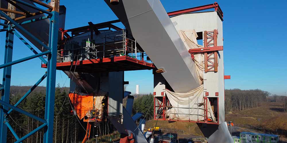
The assembly project consisted in checking the girders in each phase and in studying of the various proceedings needed to align the four segments before execution of welded joints.

The steel structure was divided into four macro-segments, entirely assembled at the construction site on the river bank by welding the elementary segments. Each of them was then hoisted up on provisional support and transported to their final location by SPTM, after being positioned at height on provisional supports that were also transported.
The assembly project consisted in checking the girders in each phase and in studying of the various proceedings needed to align the four segments before execution of welded joints.