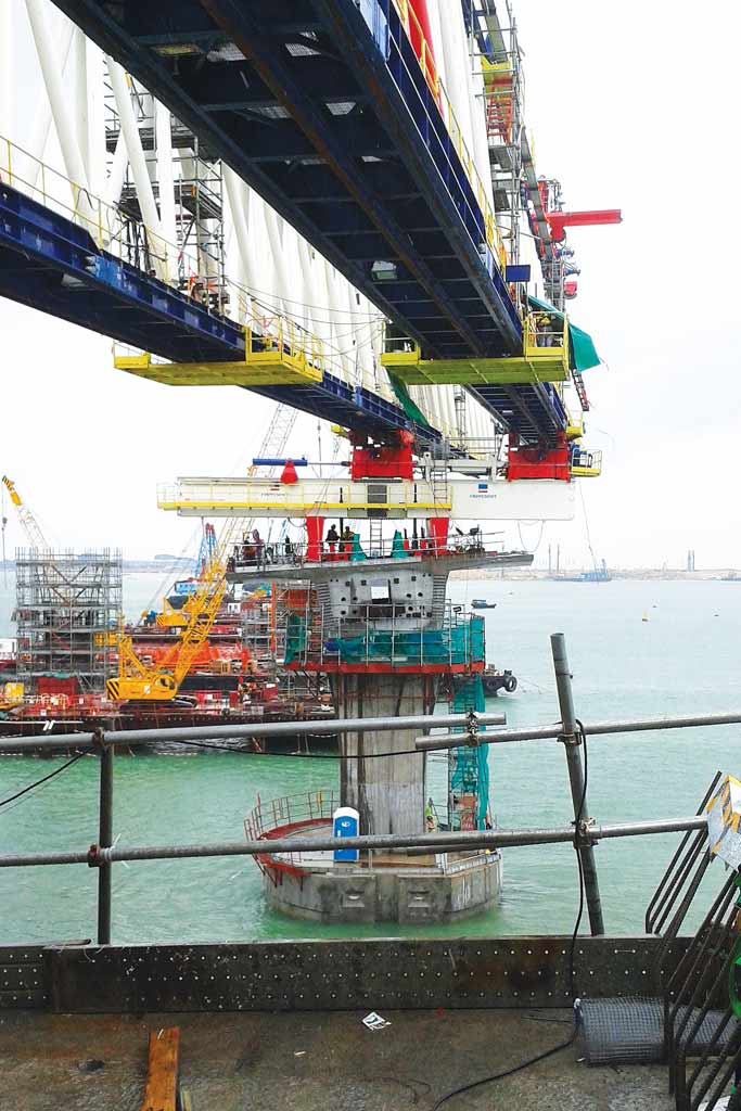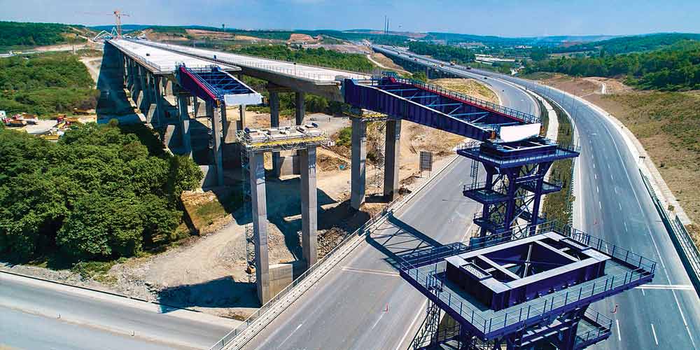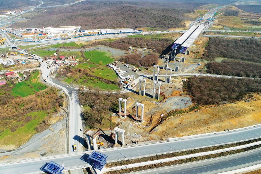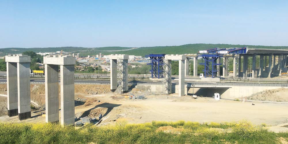
Prefabrication equipment for prestressed concrete deck built with Dywidag system.
Category: Special Equipment
Activity: Final and Construction design
Period: September 2010 – December 2010
Client: Deal s.r.l.
Value: €950,000.00 (Category IXb)
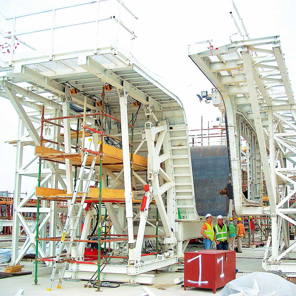
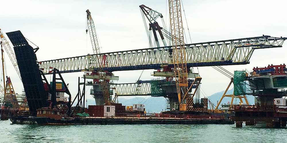
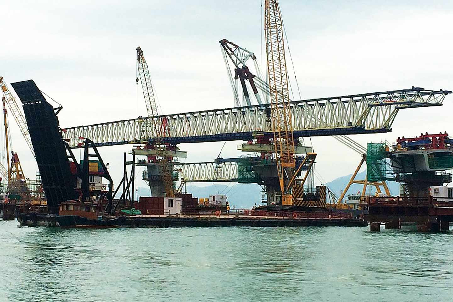
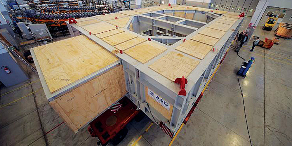
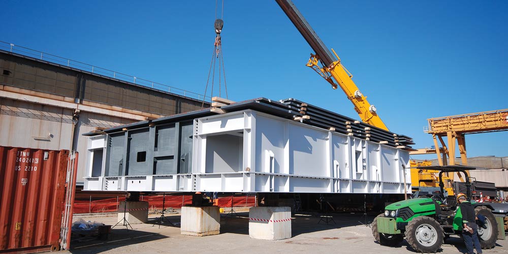
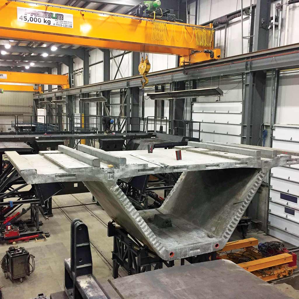
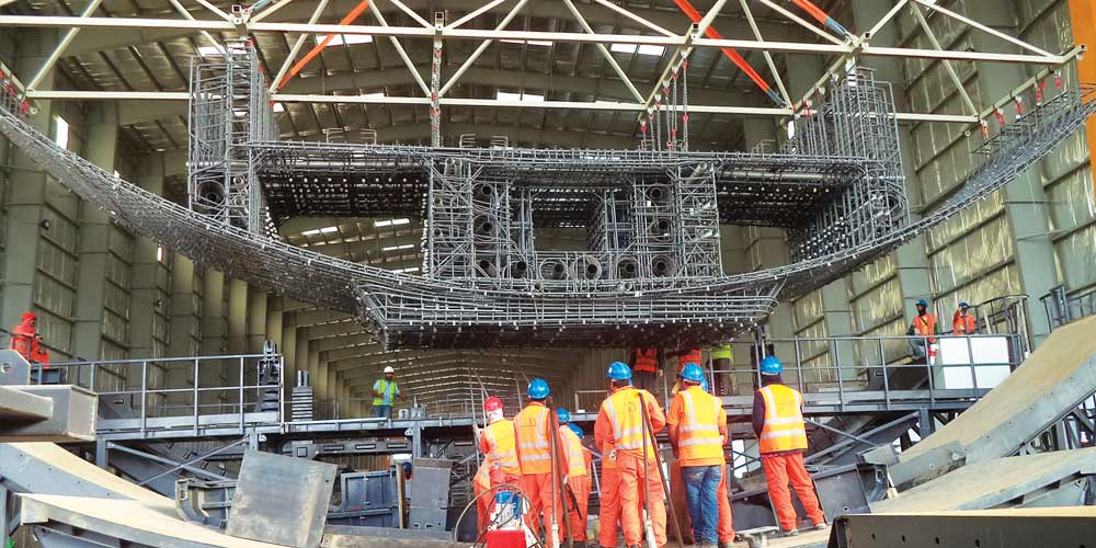
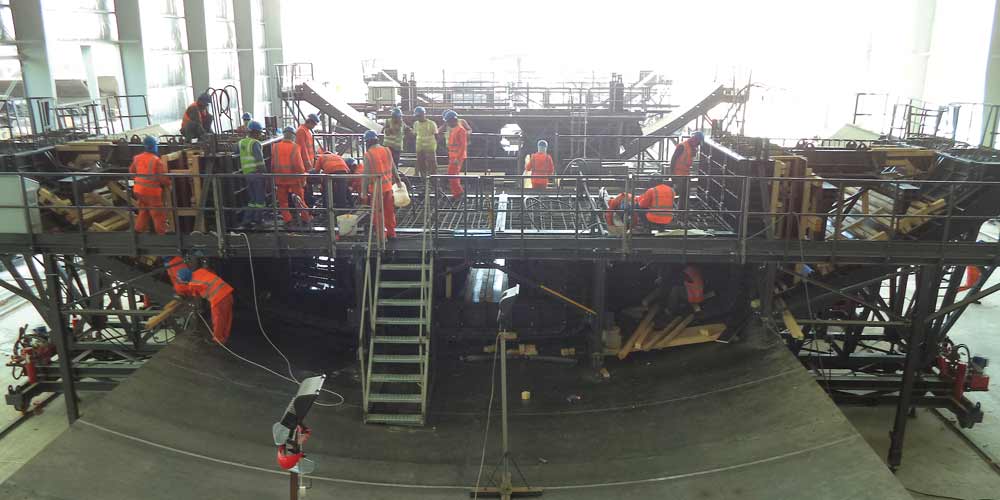
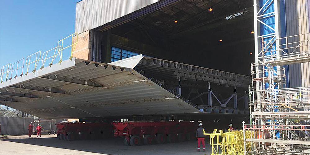
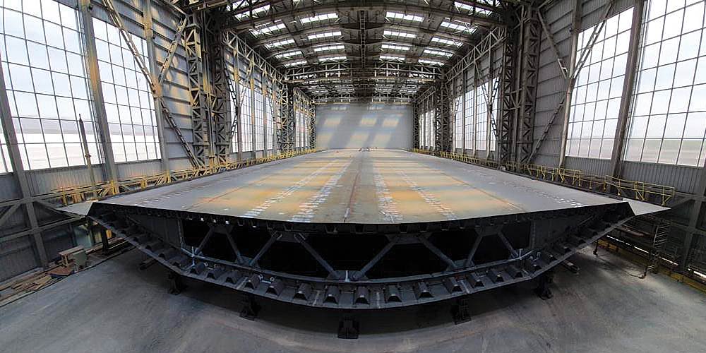
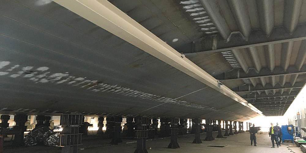
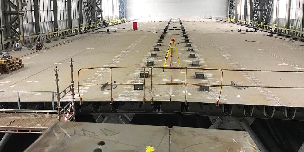
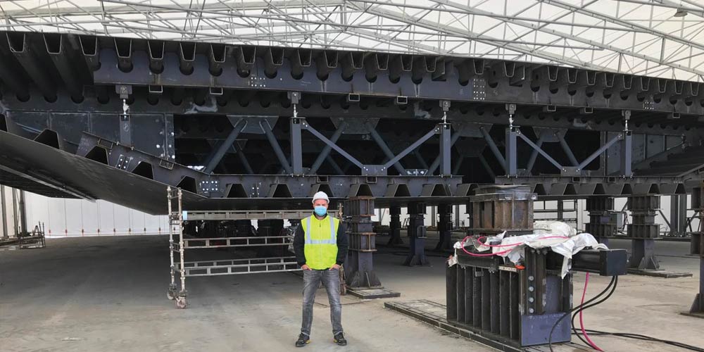
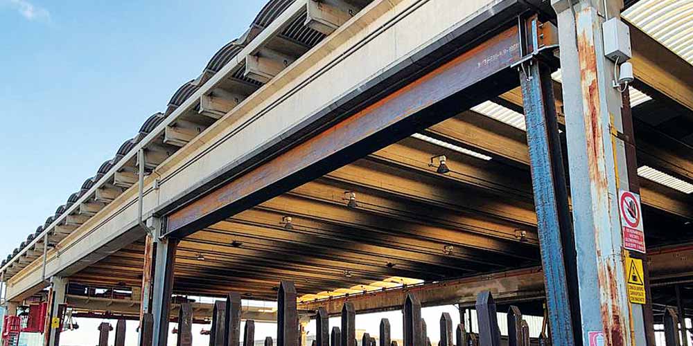
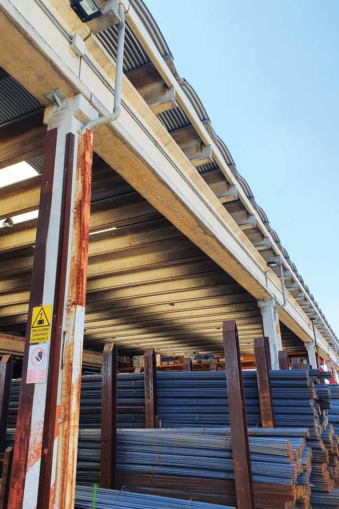
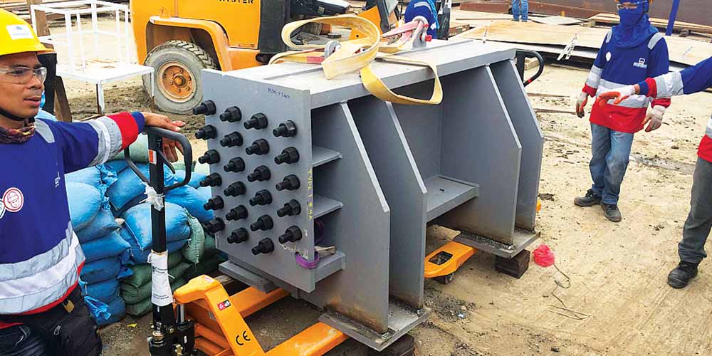
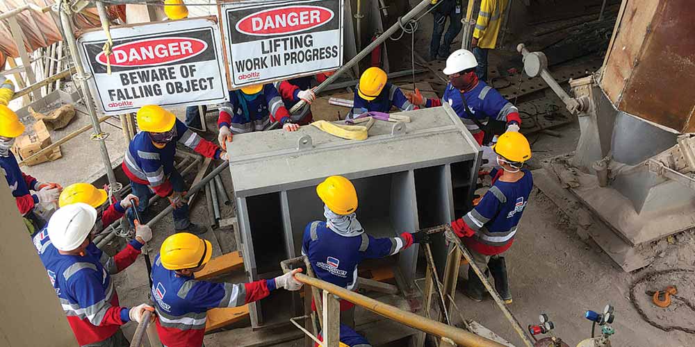
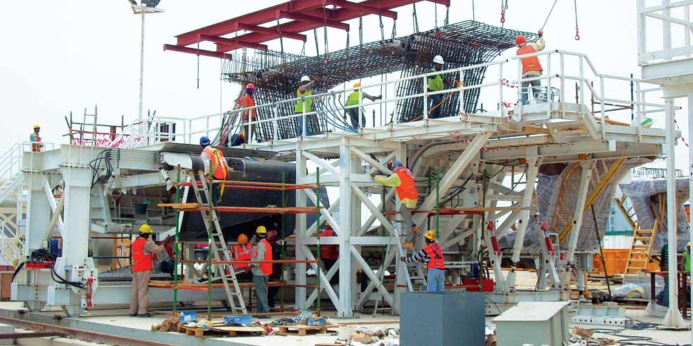
Metal structures for the load-bearing elements of the formwork for production of precast segments for a concrete deck prestressed.
Metal structures for the load-bearing elements of the formwork for production of precast segments for a concrete deck prestressed.
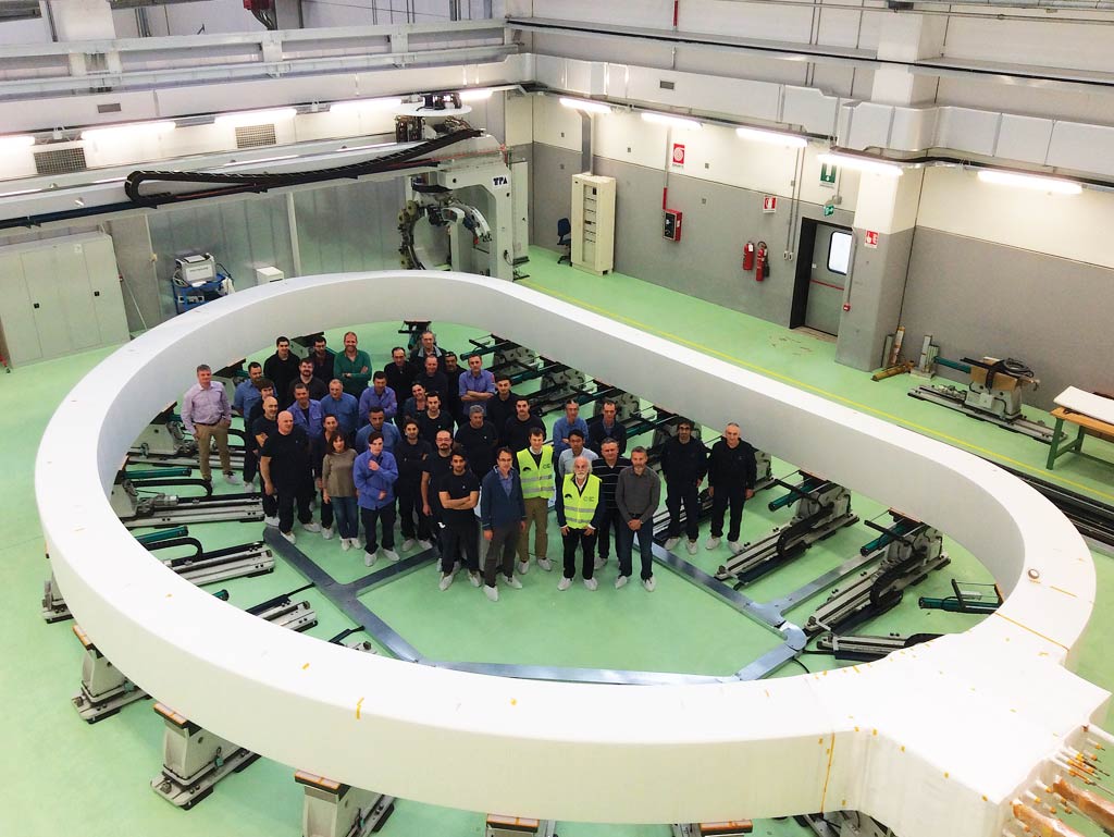
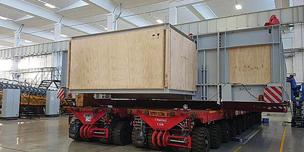
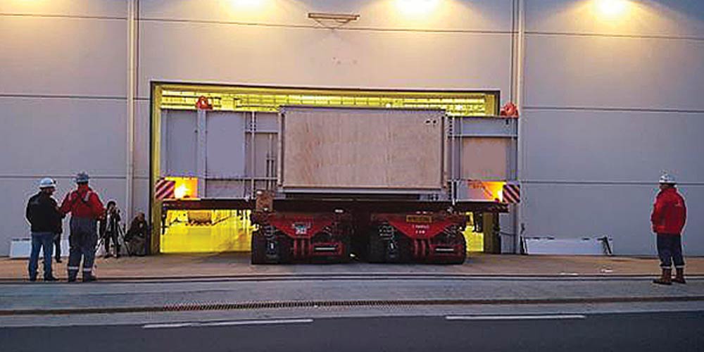
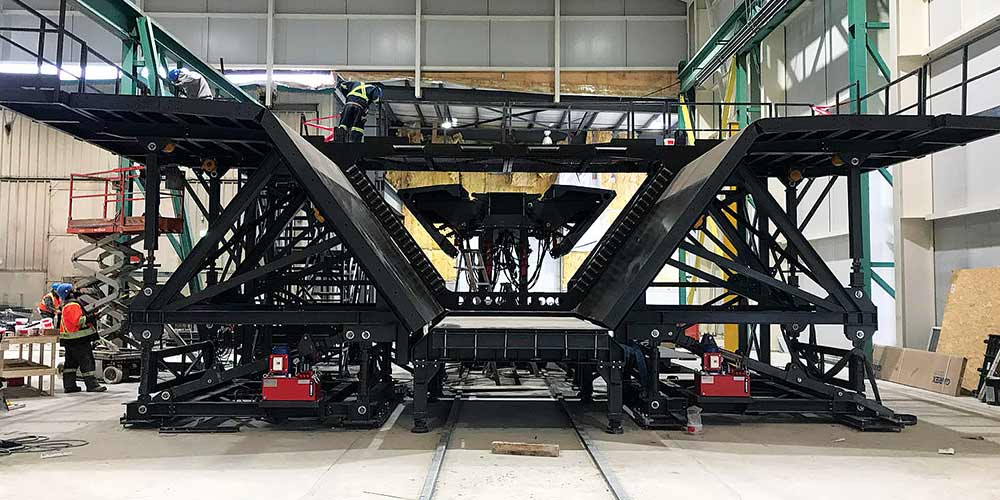
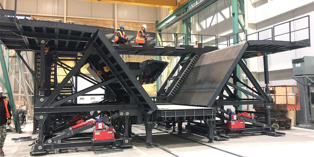
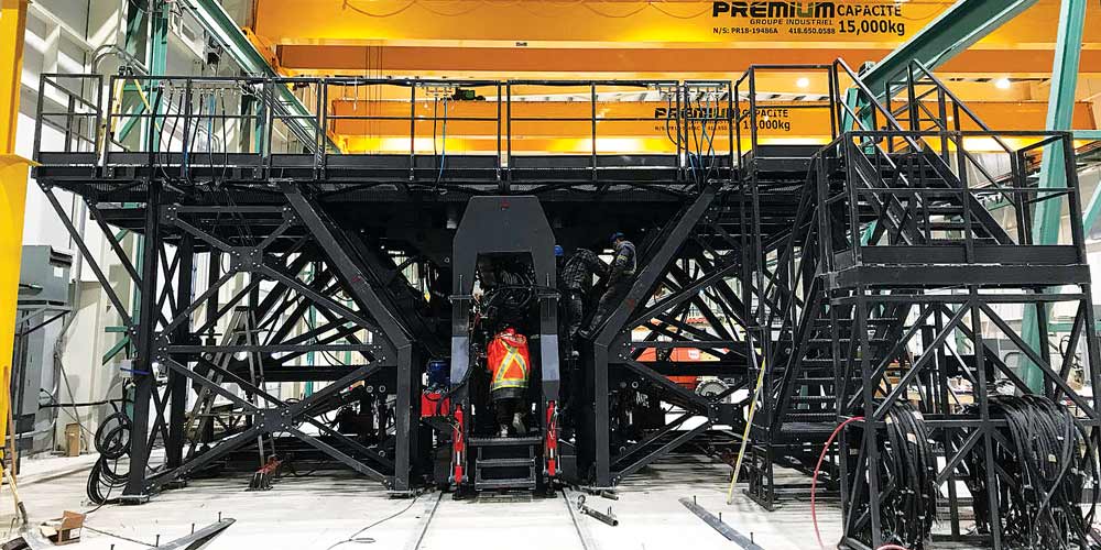
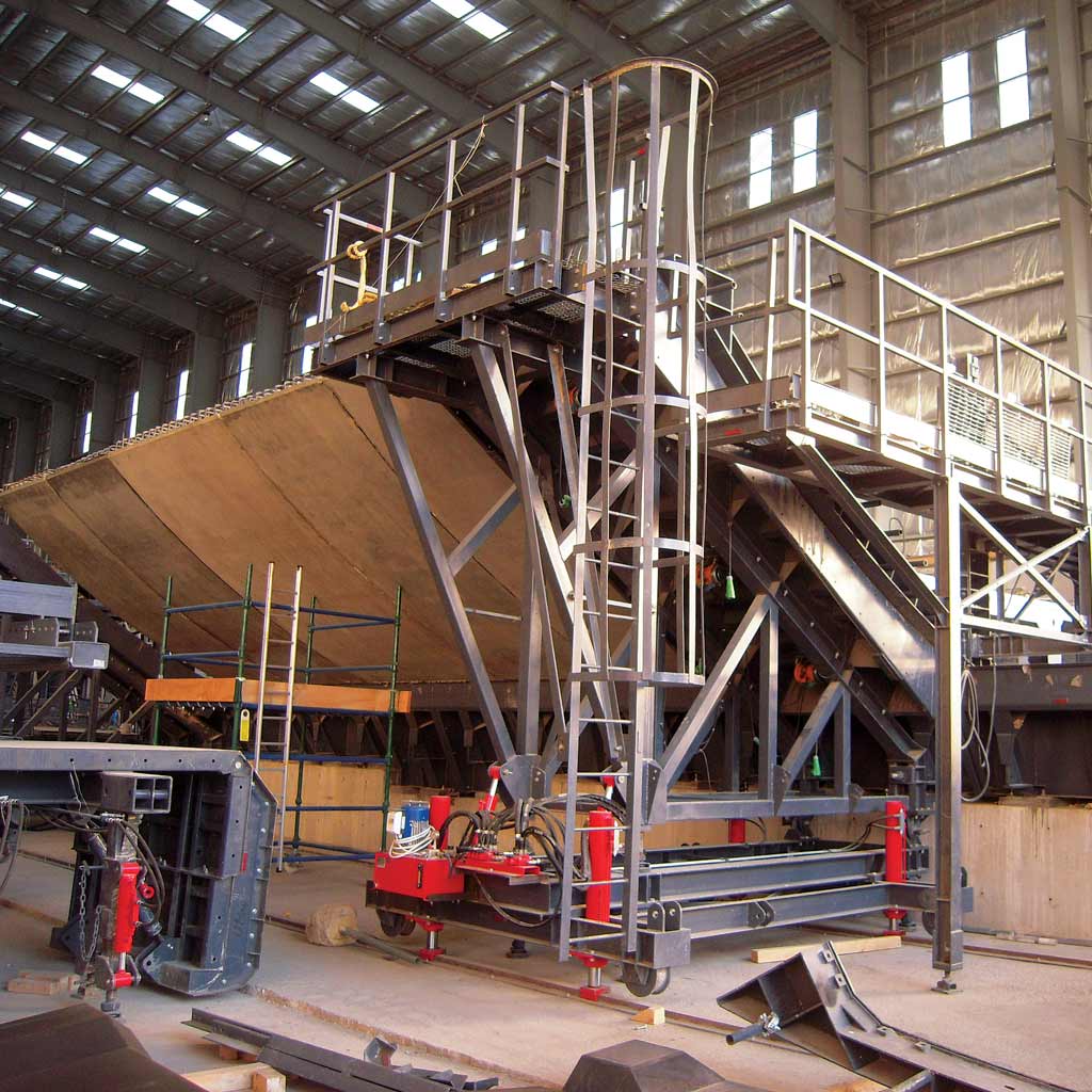
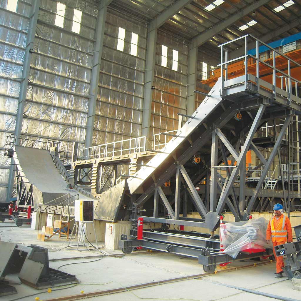
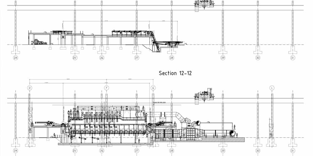
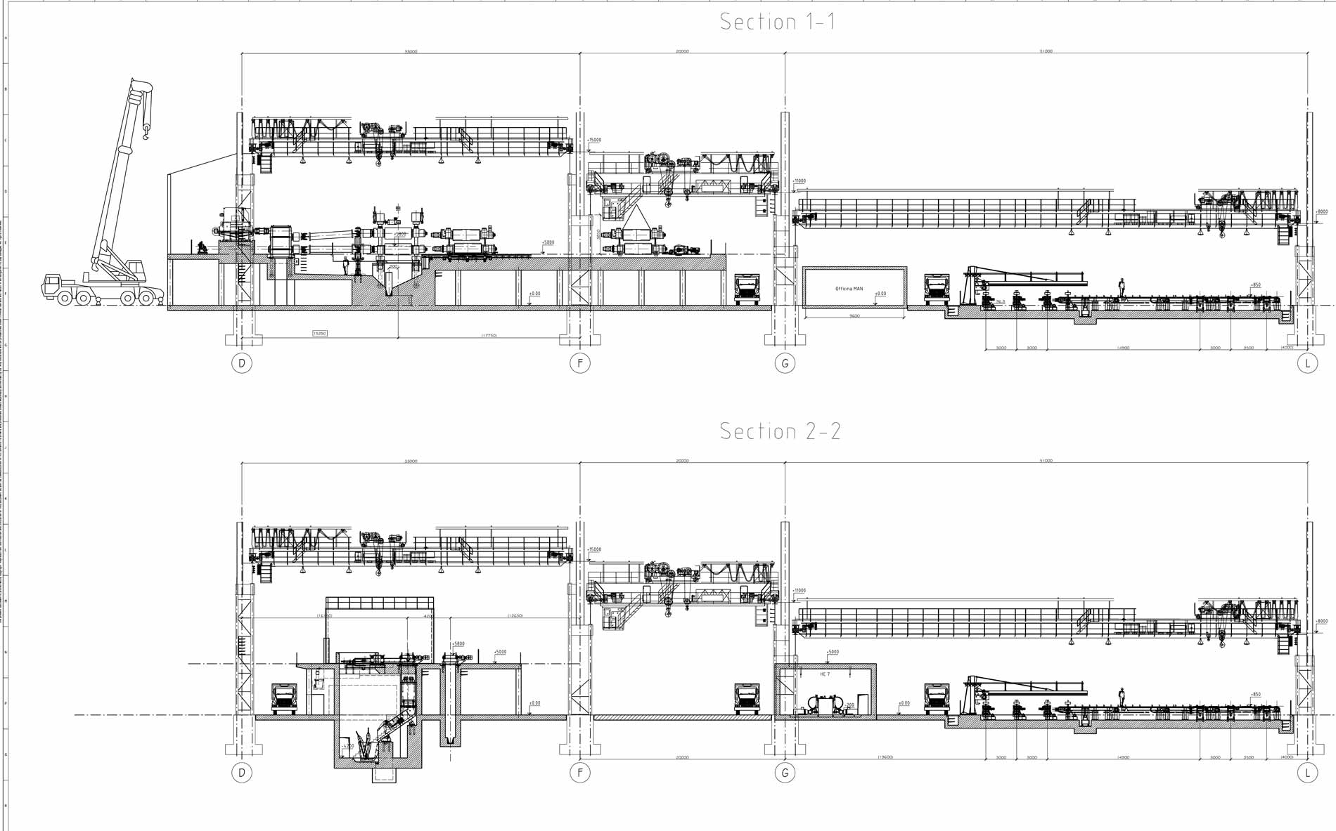
Design of the structures for the fixed part and the mobile part, retaining towers of the fixed part, trolleys to move the segments.
Design of the structures for the fixed part and the mobile part, retaining towers of the fixed part, trolleys to move the segments.
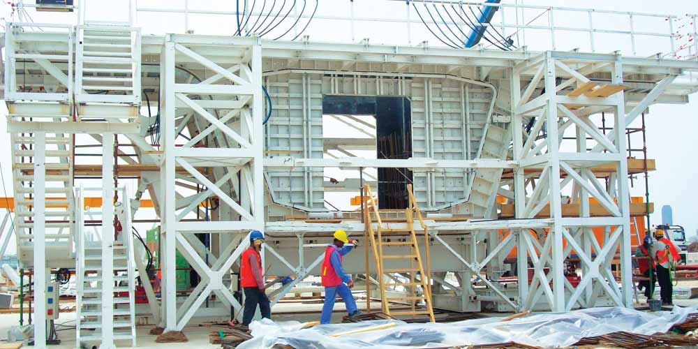
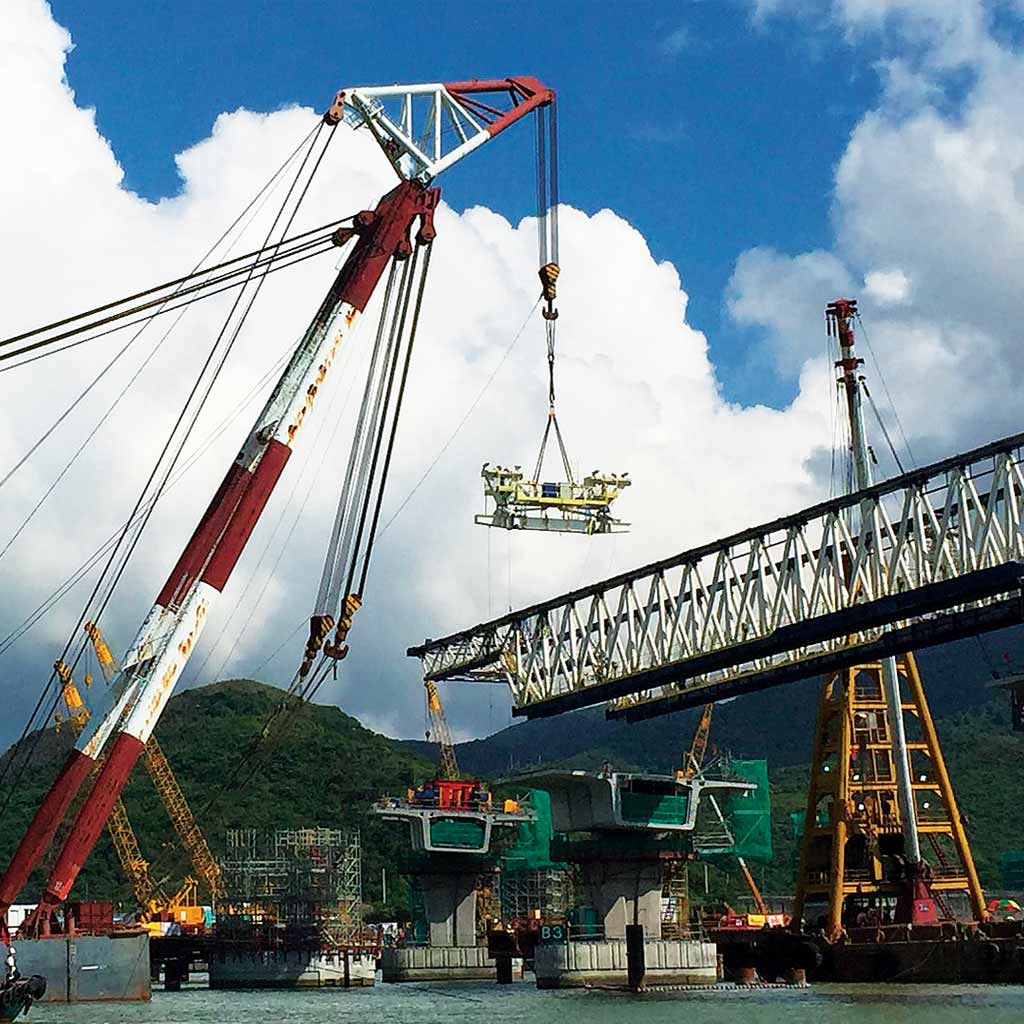
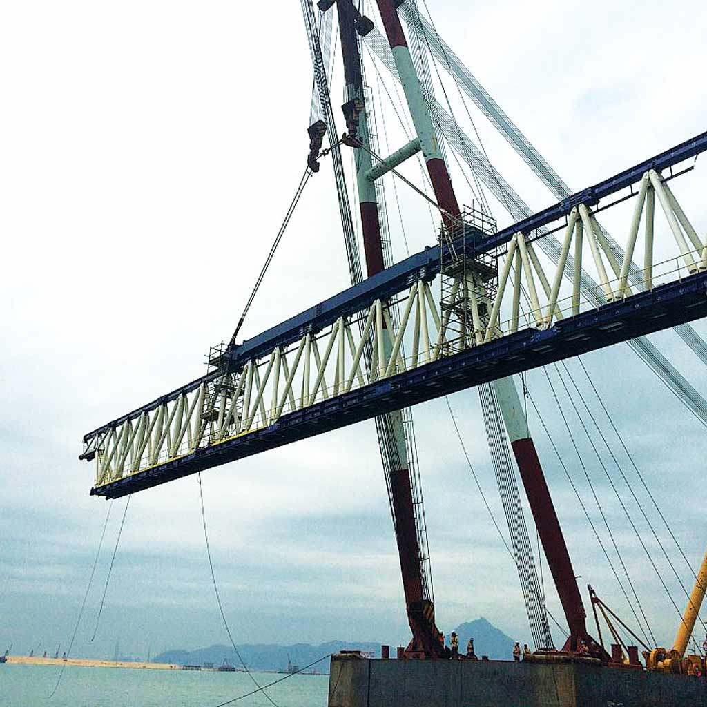
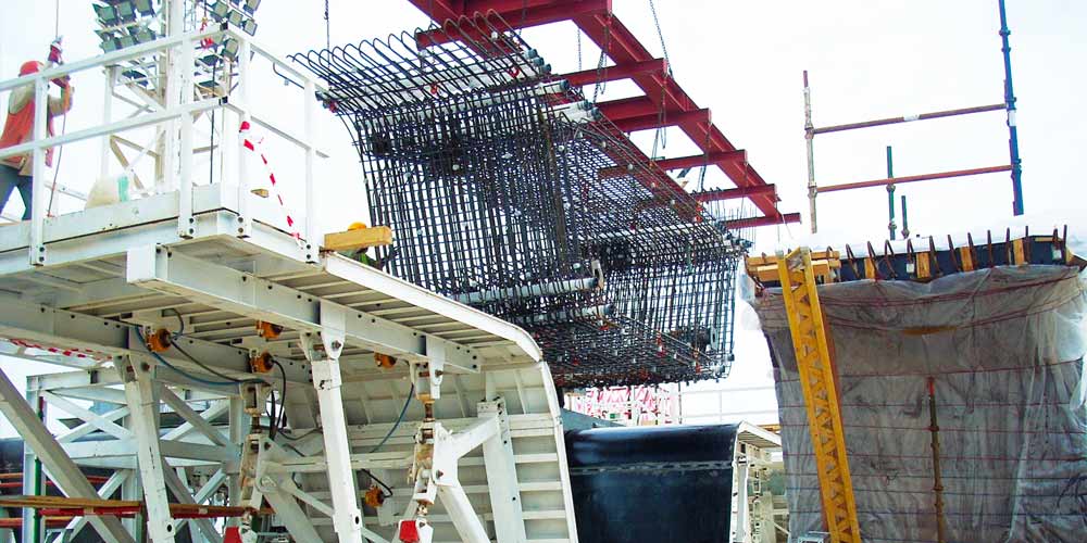
Design of the metal parts of the formwork for the on-site prefabrication of segments.
Design of the metal parts of the formwork for the on-site prefabrication of segments.
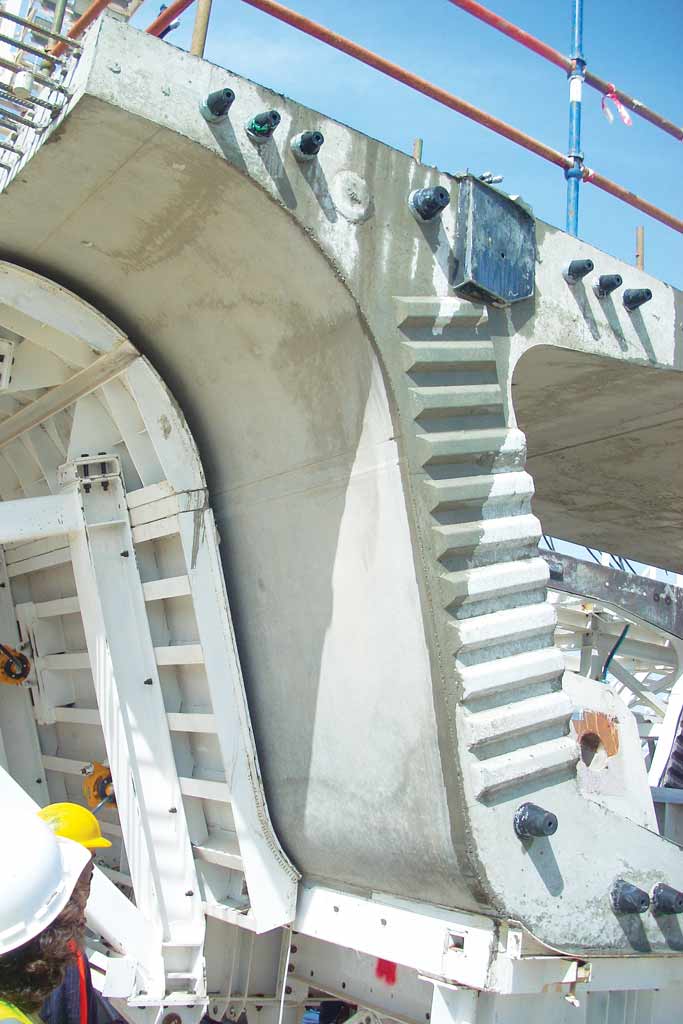
The tools are designed to adapt to three different types of segments:
• Segment at constant height – longitudinal length of 260 cm type S1, S2 (standard) and 280 cm type P4, P4A (with diaphragms)
• Segment with variable height longitudinal length of 260 cm typo S3, S4, S5 (standard) and longitudinal development of 280 cm type P1, P2, P3, P5 (with diaphragms)
• Joint voussoir – longitudinal length of i 195 cm type A1, A2 (with diaphragms)