Load test of S3 and S6 bridges and revamping after test failure.
Category: Revamping of existing structures
Services: Final Design
Period: June 2017 – December 2018
Client: WeBuild
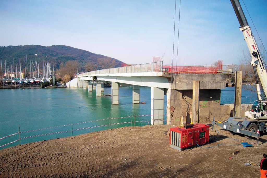
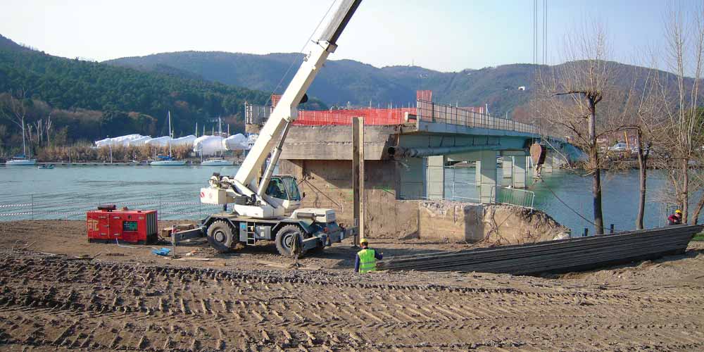
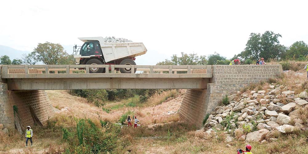
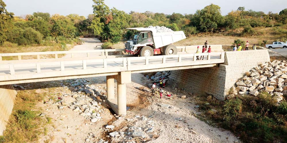
The bridge at km 8 + 382.172 on the road axis called Guba Road is composed of several spans in a single support scheme with variable length: the free spans are 15 + 20 + 15 m.
The bridge at km 8 + 382.172 on the road axis called Guba Road is composed of several spans in a single support scheme with variable length: the free spans are 15 + 20 + 15 m.
The deck, entirely made of reinforced concrete poured on site, is composed of 4 longitudinal beams 1400×360 mm and an inclined slab 200 mm thick.
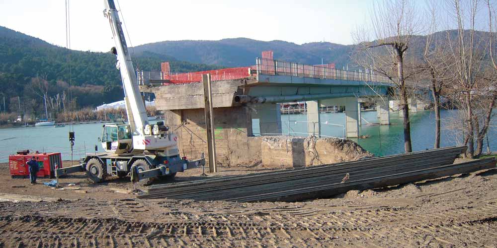
During the loading test, abnormal deflections were measured and diagonal shear cracks appeared due to the poor quality of the materials used.
The deck, entirely made of reinforced concrete poured on site, is composed of 4 longitudinal beams 1400×360 mm and an inclined slab 200 mm thick.
During the loading test, abnormal deflections were measured and diagonal shear cracks appeared due to the poor quality of the materials used.
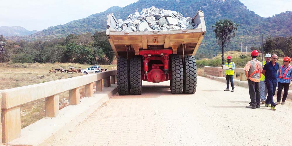
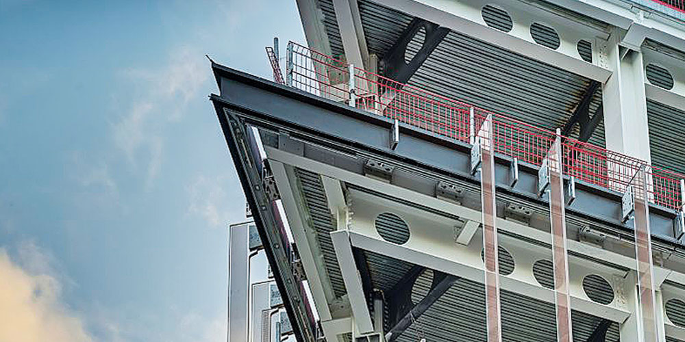
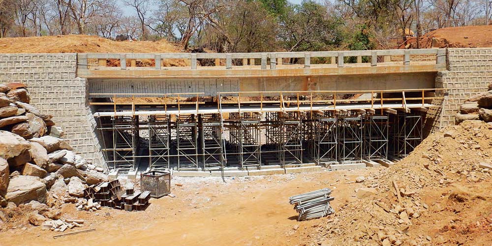
It was therefore necessary to carry out the shear reinforcement of the longitudinal beams, which was carried out by “lining” the beams themselves with very high strength concrete (Rck 65 MPa) to a thickness of 50 mm, after removal of the concrete cover.
It was therefore necessary to carry out the shear reinforcement of the longitudinal beams, which was carried out by “lining” the beams themselves with very high strength concrete (Rck 65 MPa) to a thickness of 50 mm, after removal of the concrete cover.