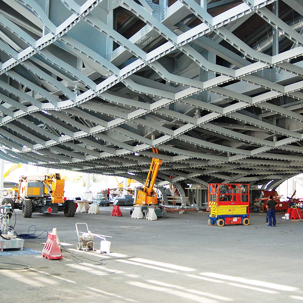
Detailed design of the steel structures above ground of the hangar.
Category: Industrial Buildings
Services: Final detailed design
Period: April 2019 – December 2019
Client: Fincantieri Infrastructure
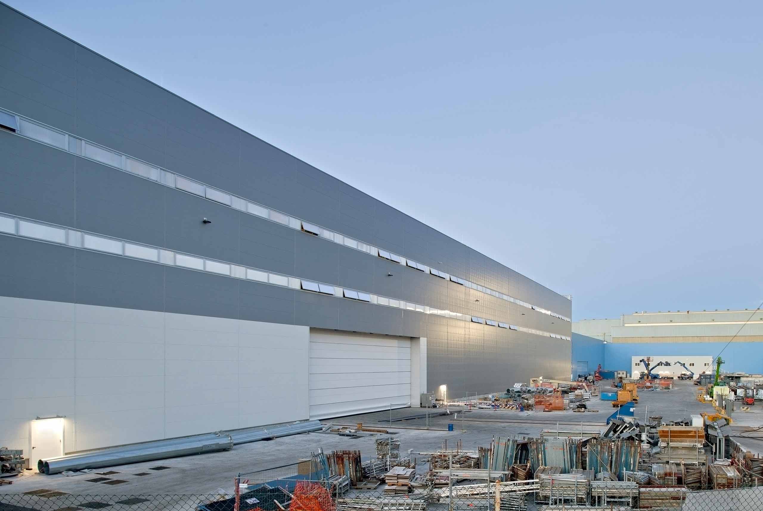
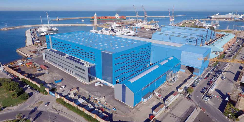
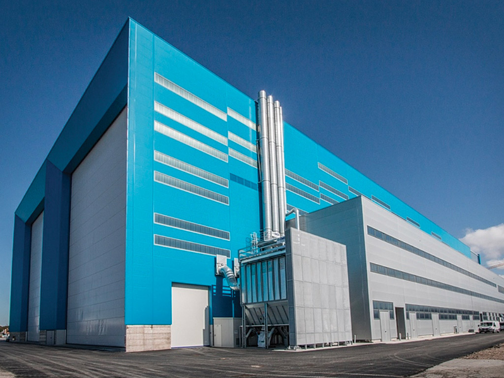
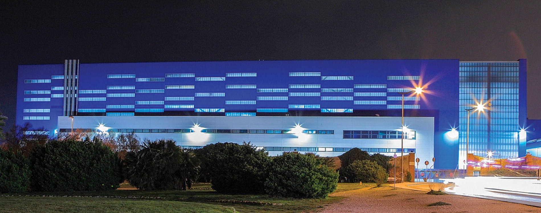
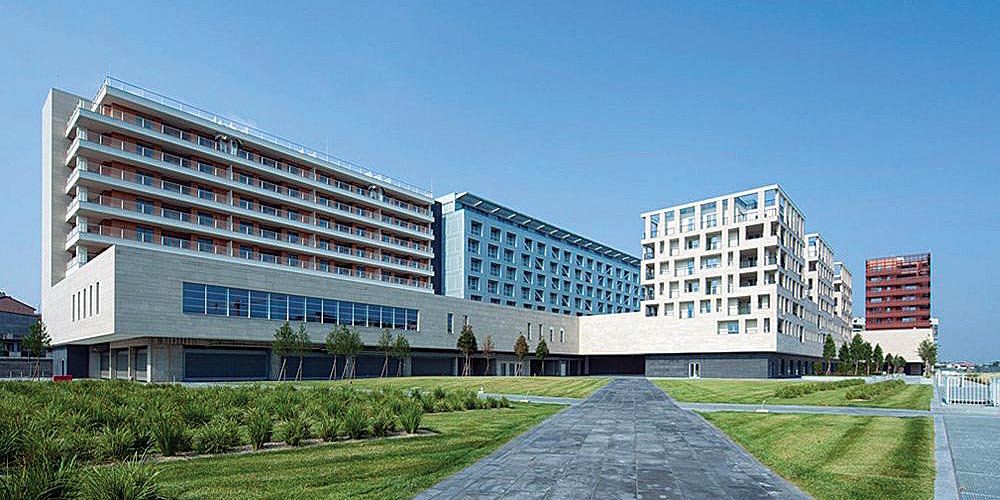
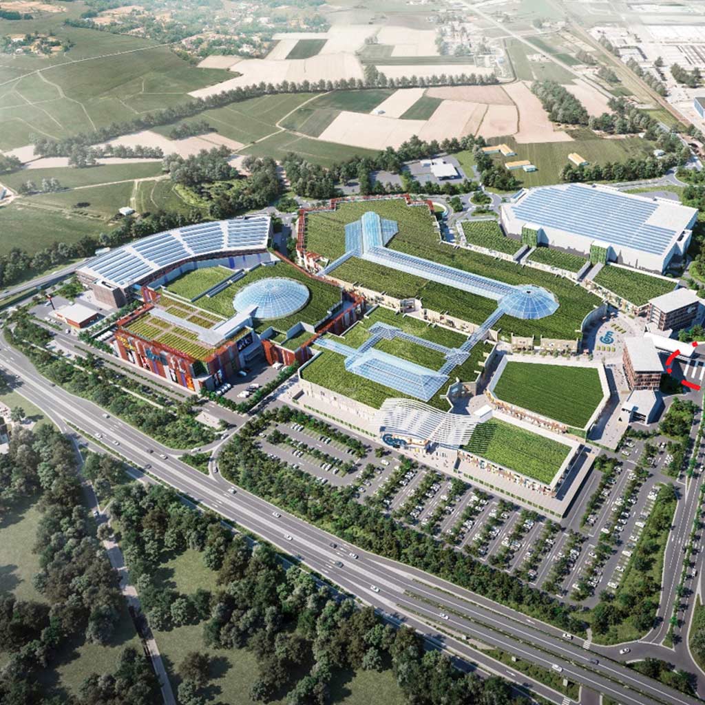
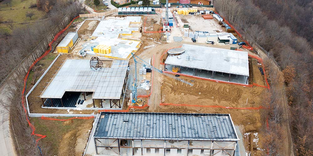
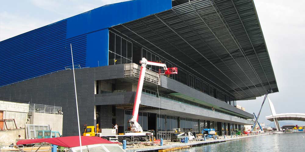
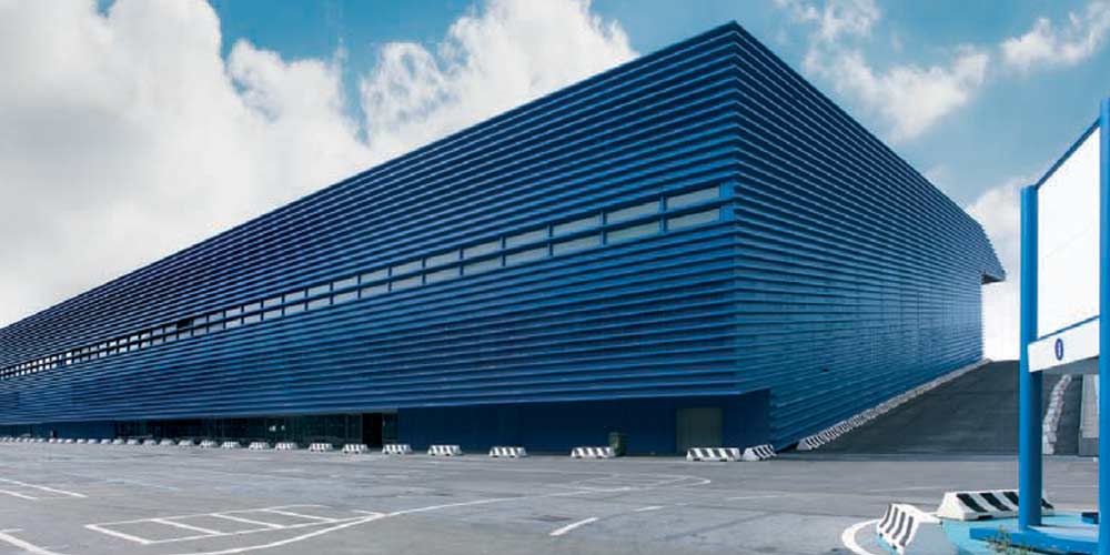
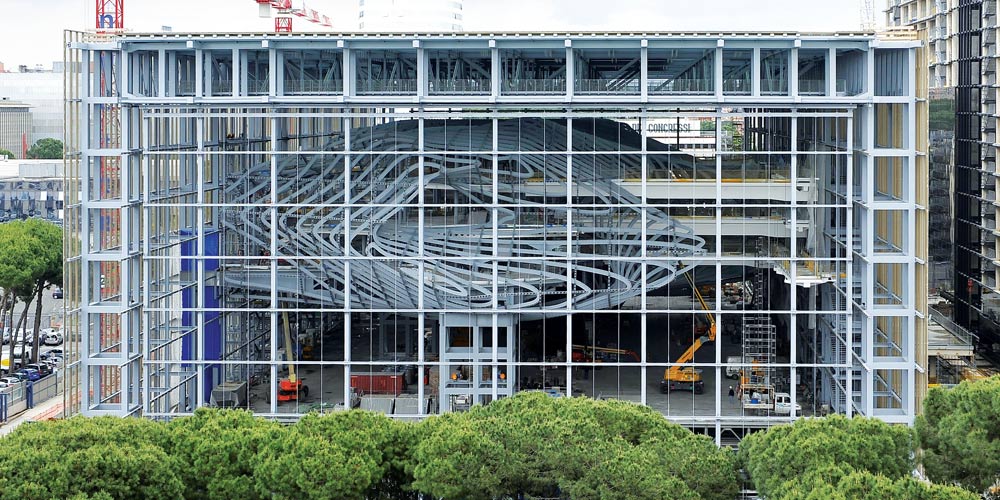
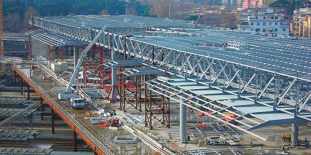
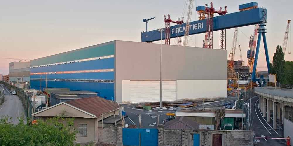
Design of the metal structure of a hangar used as a naval workshop for the expansion of the Naval Workshop on the North-West side of the shipyard of the Marghera (VE) plant. The intervention occupies a total area of approximately 44,000 square meters, of which 7,800 square meters dedicated to the new workshop and the remainder intended for the yard where the pre – assembly areas are to be built.
Design of the metal structure of a hangar used as a naval workshop for the expansion of the Naval Workshop on the North-West side of the shipyard of the Marghera (VE) plant. The intervention occupies a total area of approximately 44,000 square meters, of which 7,800 square meters dedicated to the new workshop and the remainder intended for the yard where the pre – assembly areas are to be built.
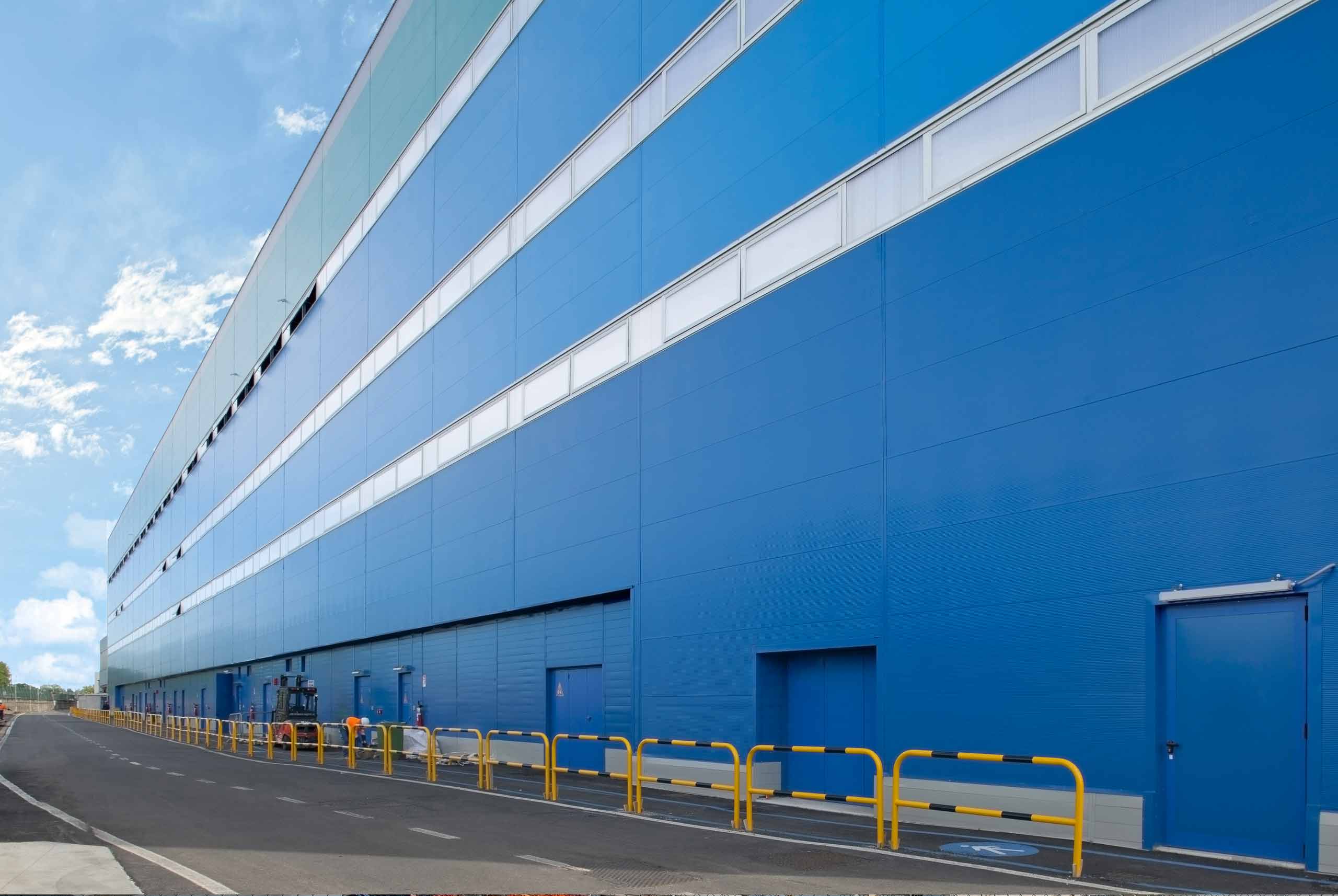
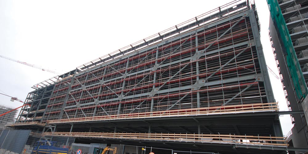
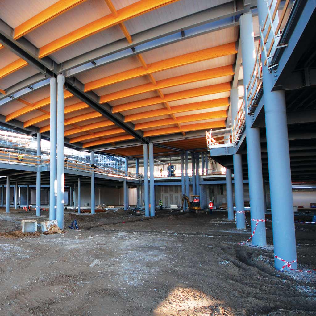
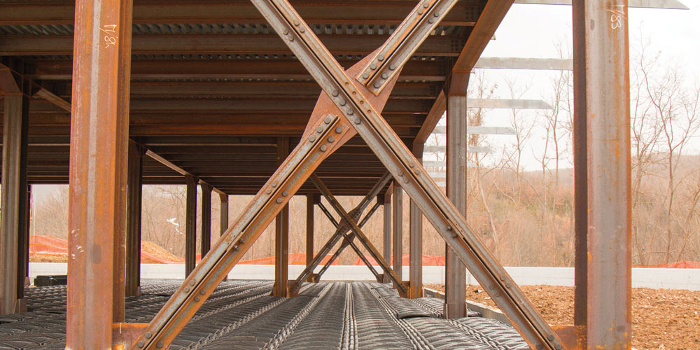
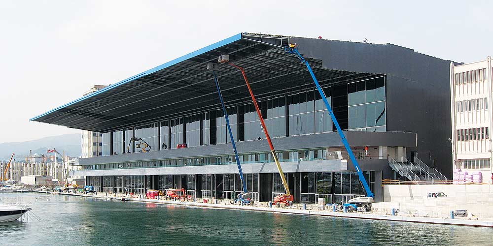
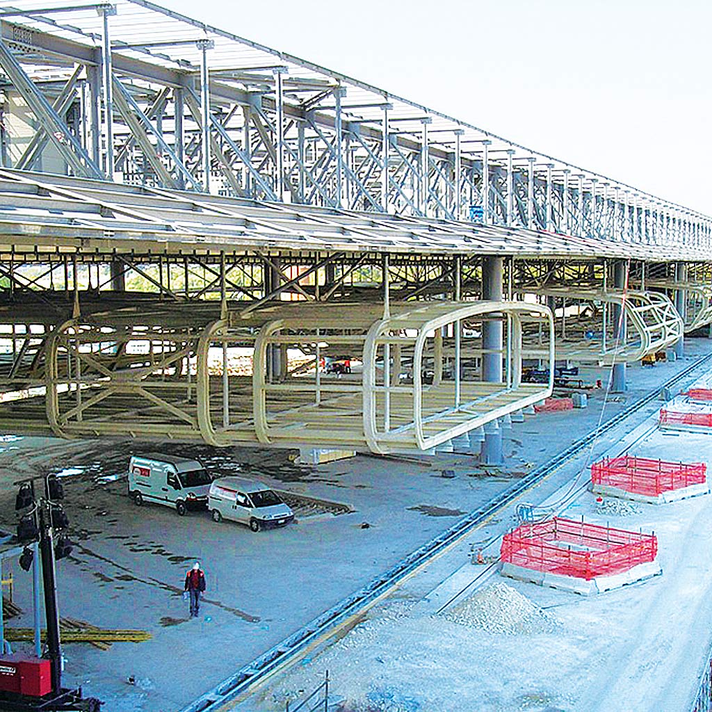
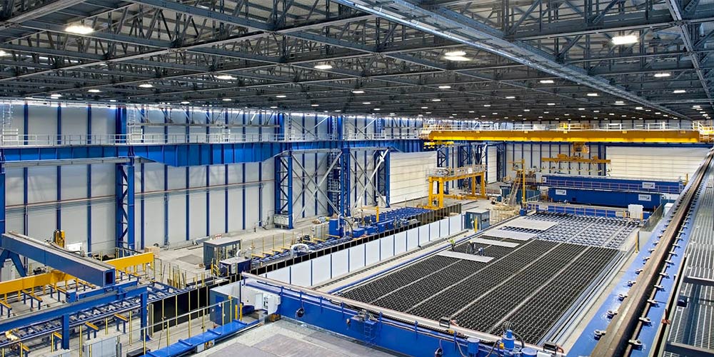
The building consists of a single- storey portal structure with a rectangular plan with dimensions of approximately 145.00 x 57.70 m and a height of approximately 21.20 m from the finished internal floor to the ridge of the roof. The building is divided into two structural parts, perfectly symmetrical, separated by an expansion joint. From the point of view of the overall static scheme, the portals are hinged to the foot in longitudinal direction in order to create a longitudinal pendular scheme whose stabilization is guaranteed by longitudinal cross braces.
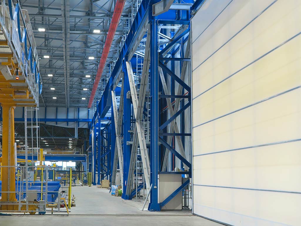
The building consists of a single- storey portal structure with a rectangular plan with dimensions of approximately 145.00 x 57.70 m and a height of approximately 21.20 m from the finished internal floor to the ridge of the roof. The building is divided into two structural parts, perfectly symmetrical, separated by an expansion joint. From the point of view of the overall static scheme, the portals are hinged to the foot in longitudinal direction in order to create a longitudinal pendular scheme whose stabilization is guaranteed by longitudinal cross braces.
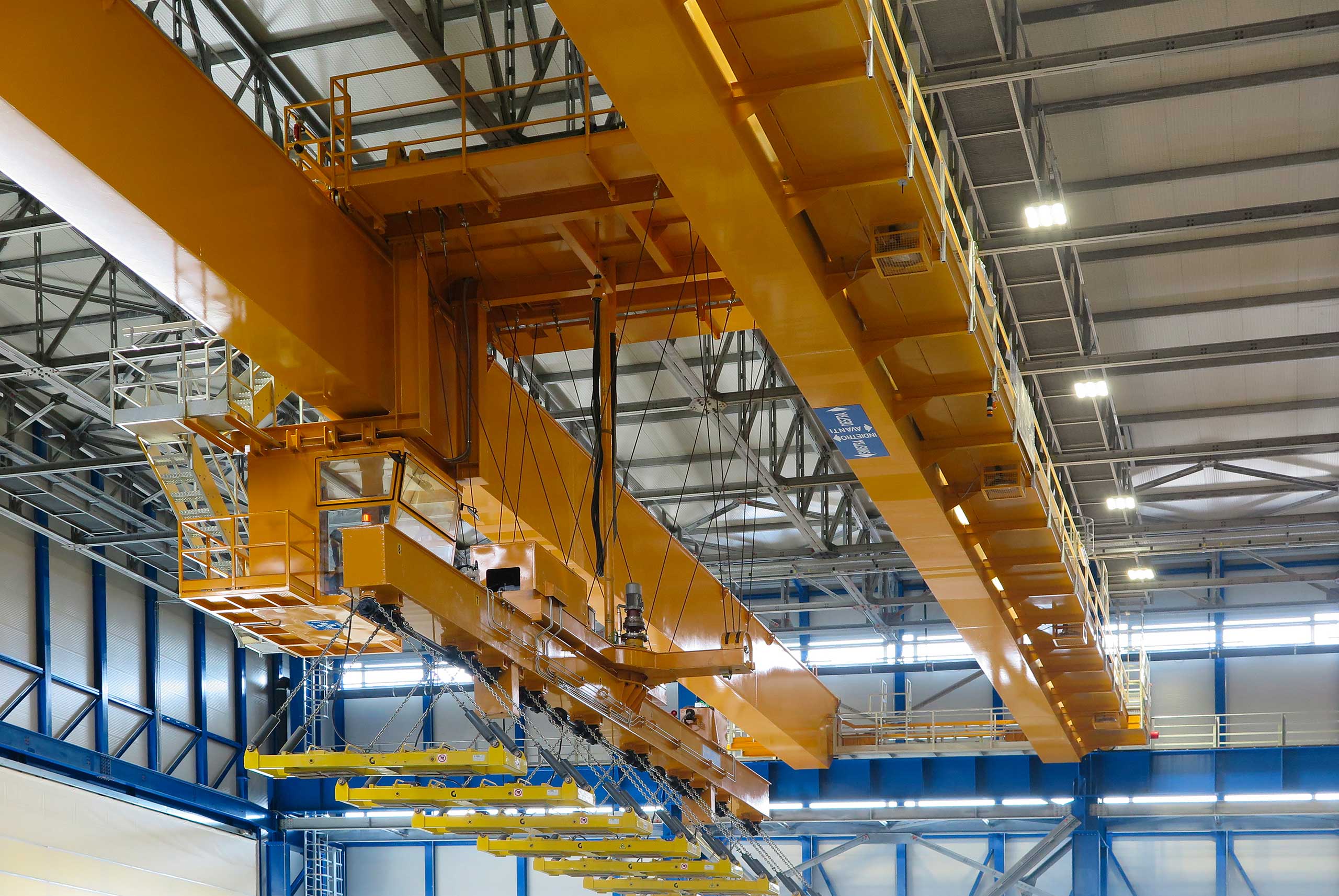
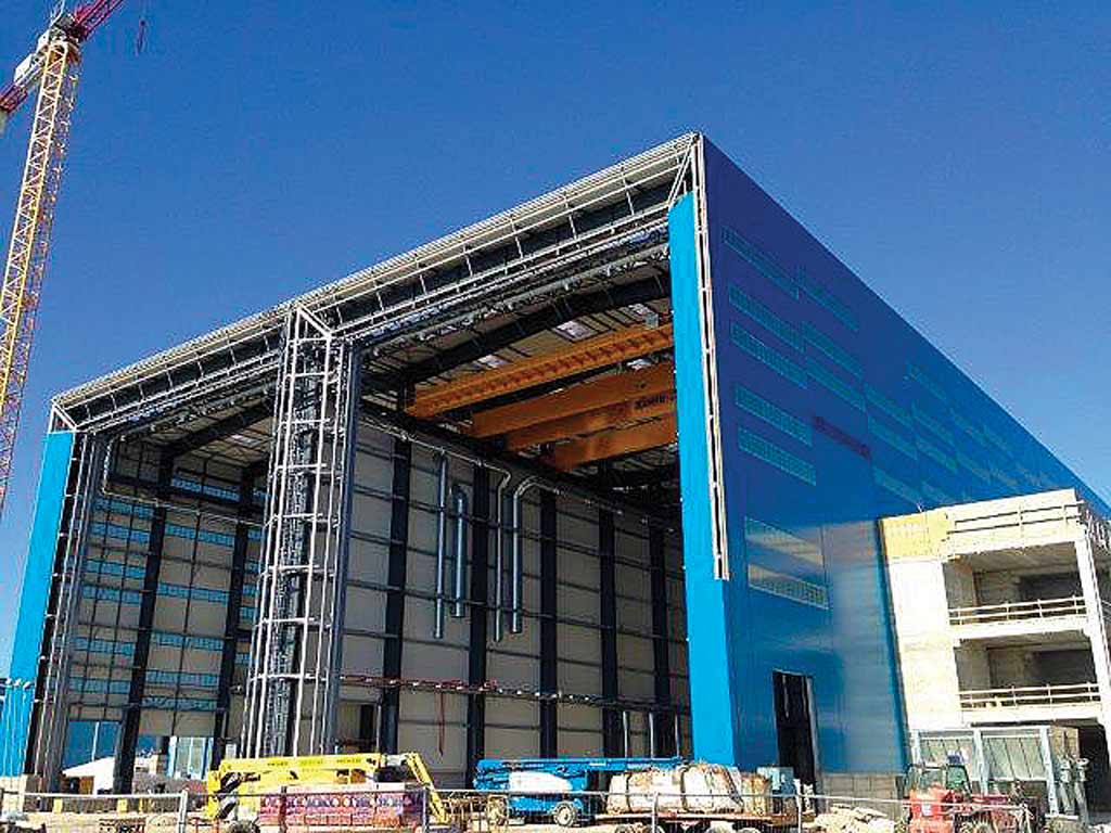
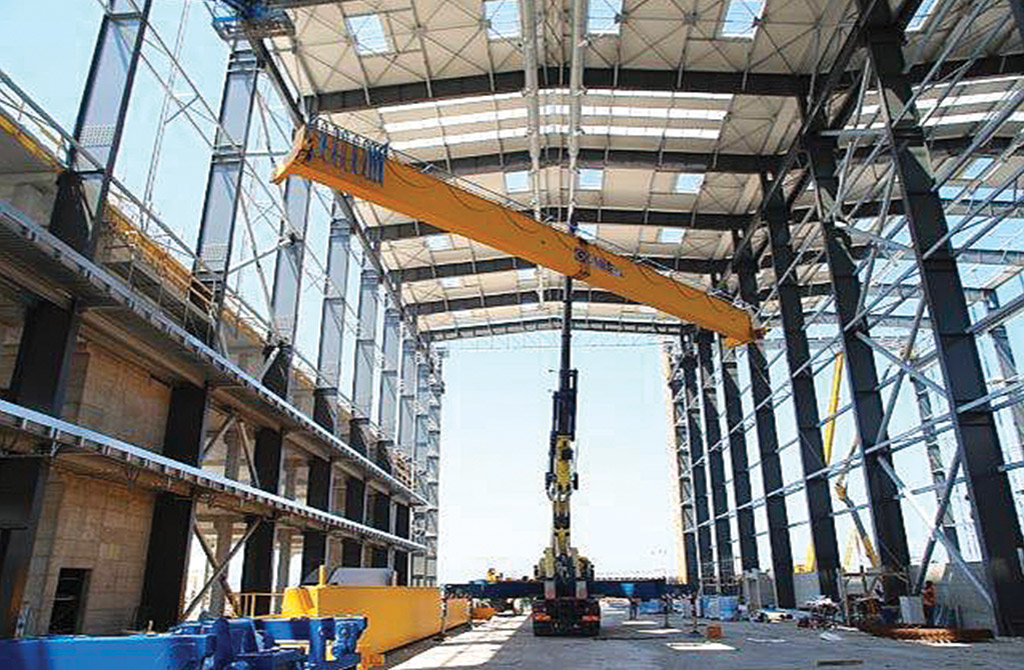
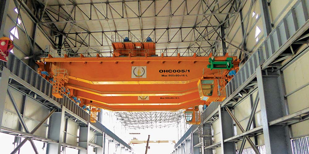
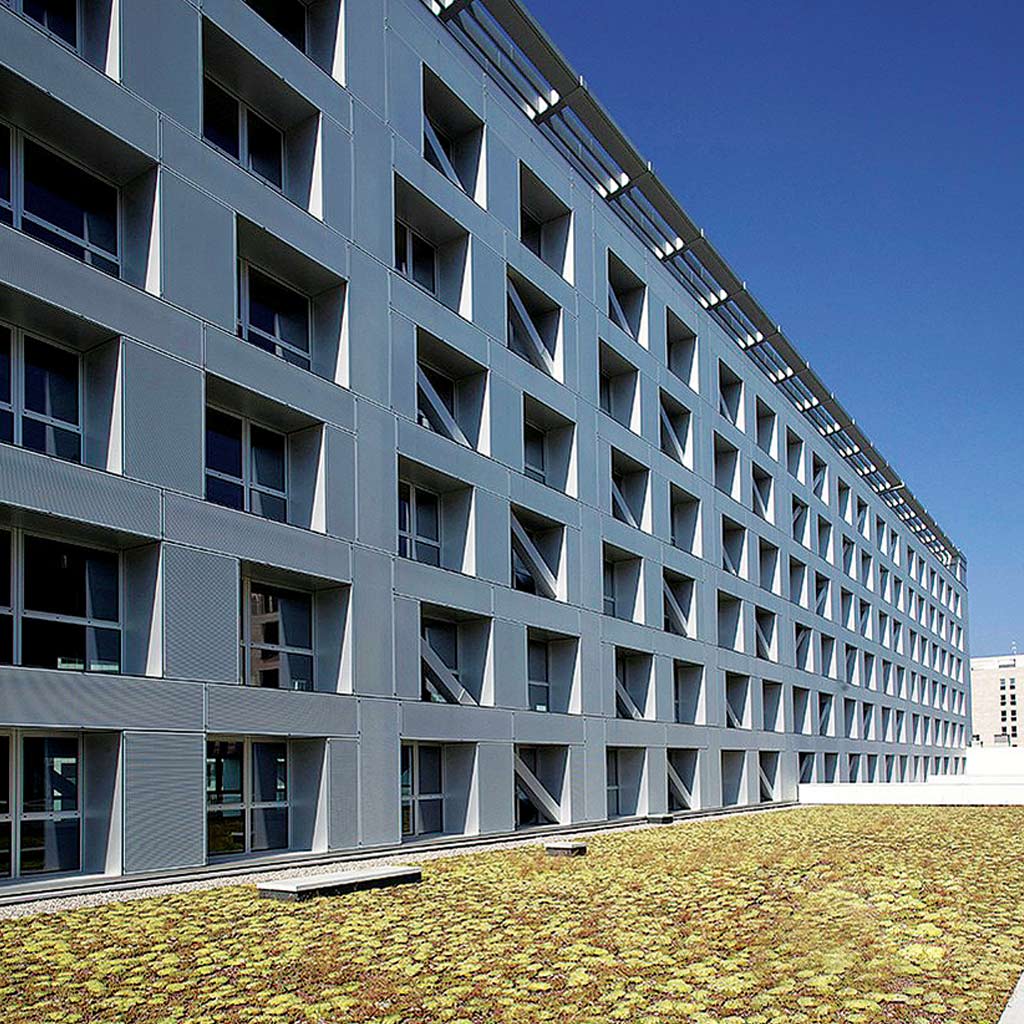
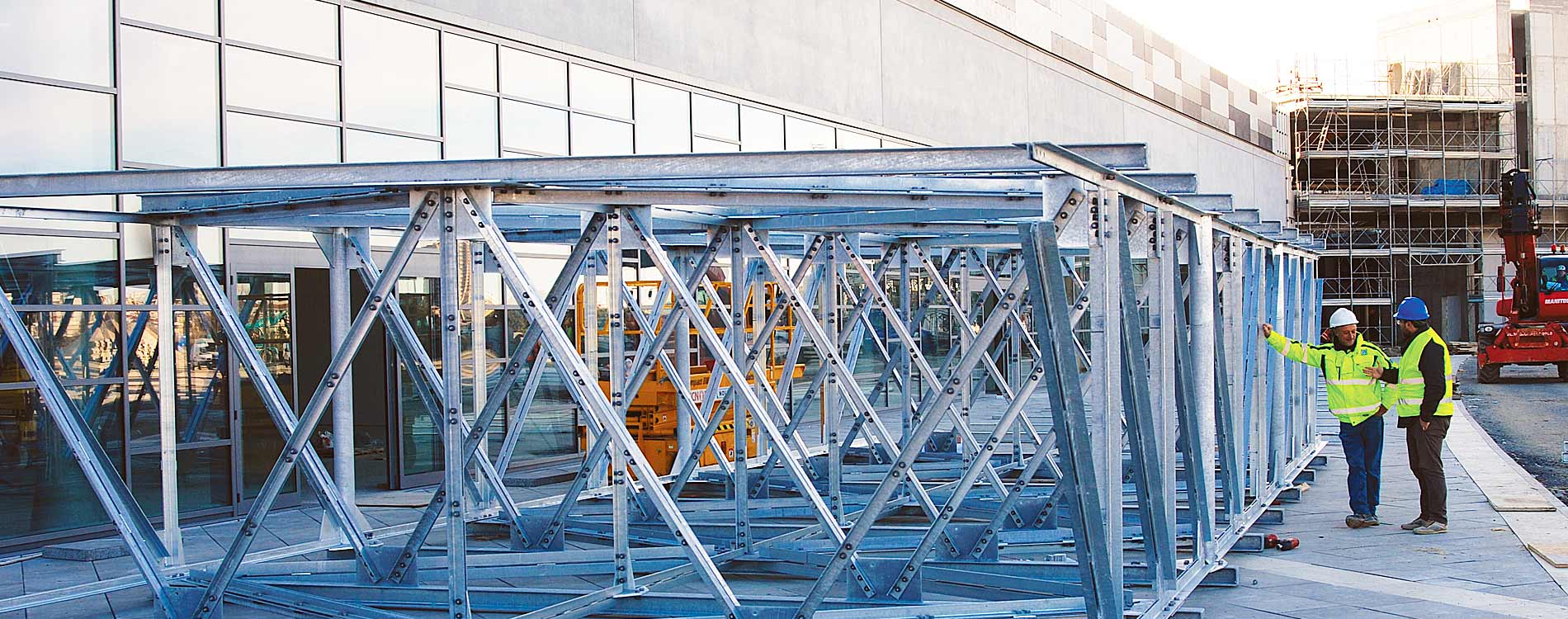
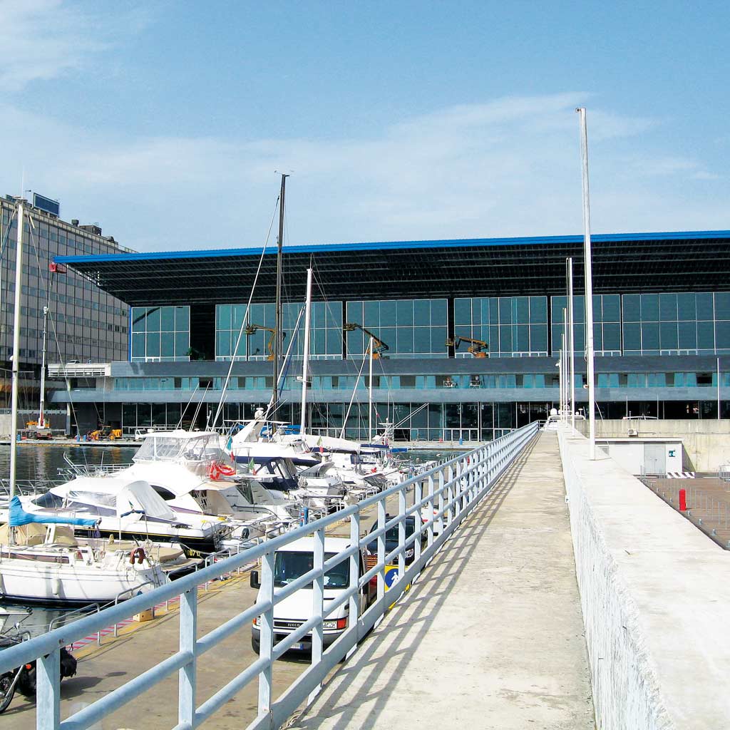
At an altitude of 11.40 m there is a runway supporting two overhead cranes: a hook crane with a capacity of 20 tons and a magnetic traverse crane with a capacity of 19 tons. The runway has a welded I-section with variable height. The side walls are made with a secondary framing placed horizontally with a vertical center distance of about 2500 mm directly supported by the transversal portals and by intermediate curtain walls mullions.
At an altitude of 11.40 m there is a runway supporting two overhead cranes: a hook crane with a capacity of 20 tons and a magnetic traverse crane with a capacity of 19 tons. The runway has a welded I-section with variable height. The side walls are made with a secondary framing placed horizontally with a vertical center distance of about 2500 mm directly supported by the transversal portals and by intermediate curtain walls mullions.