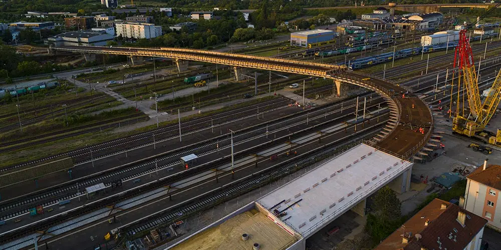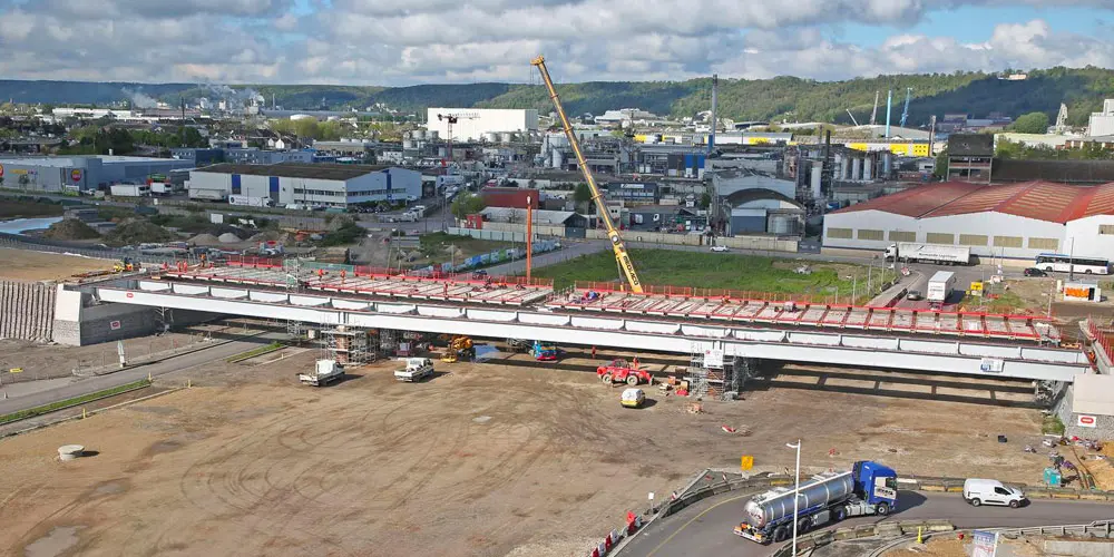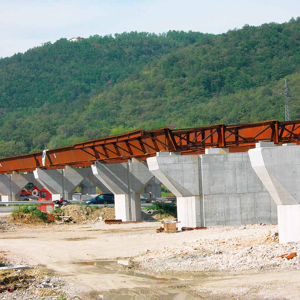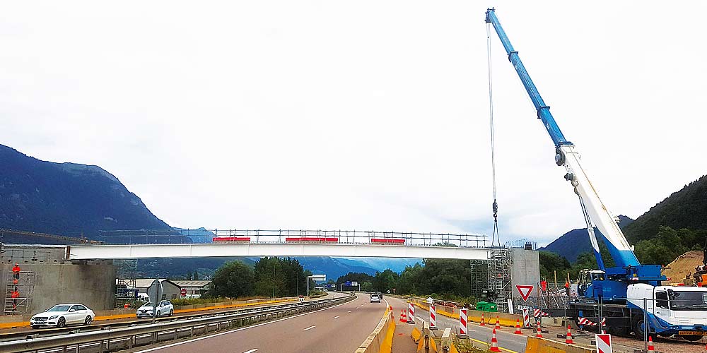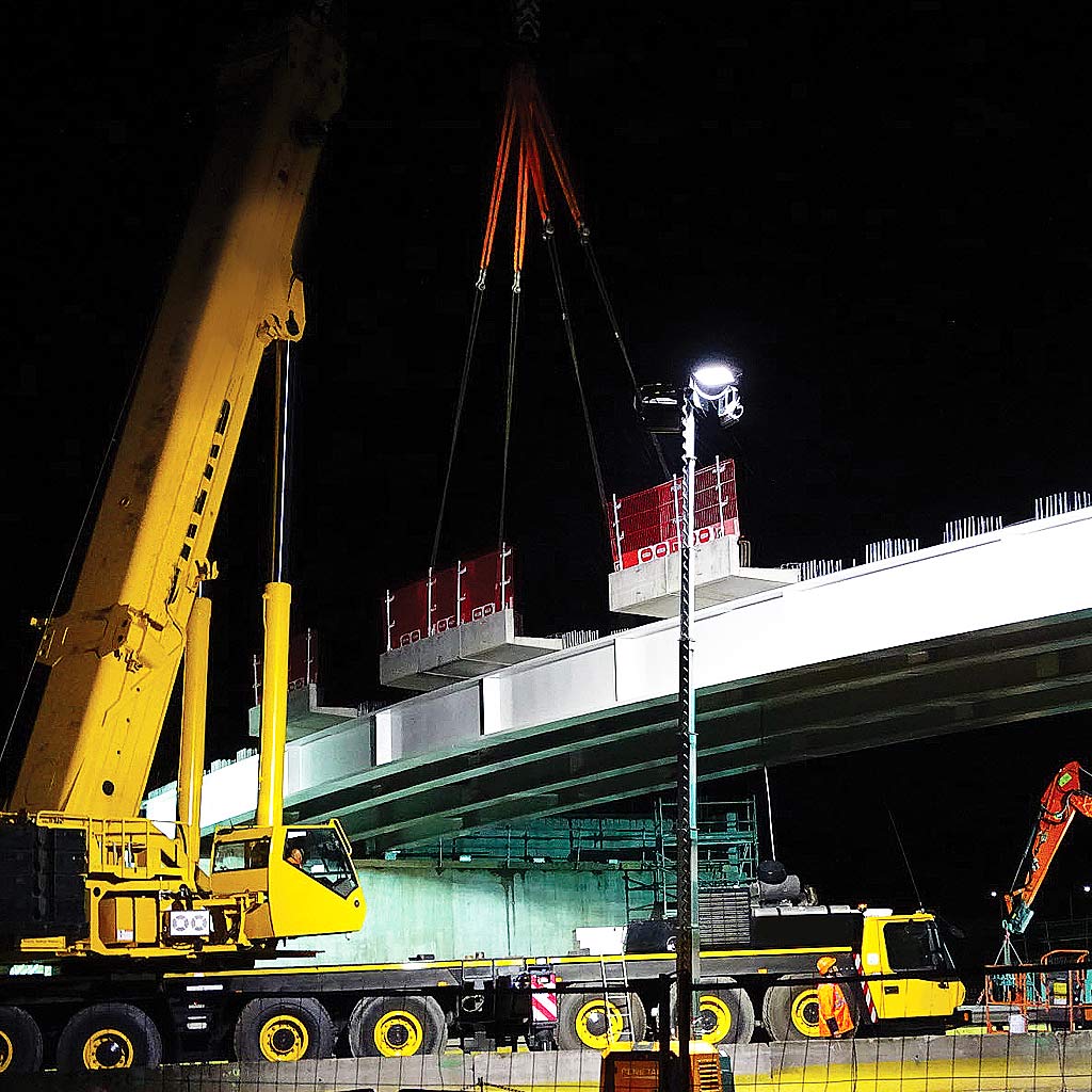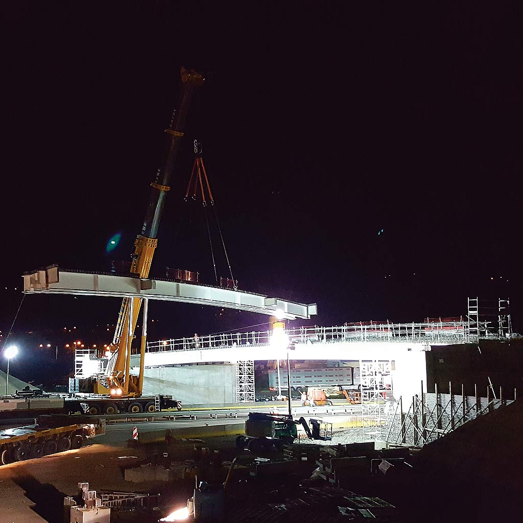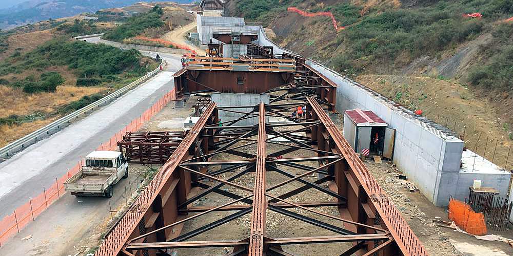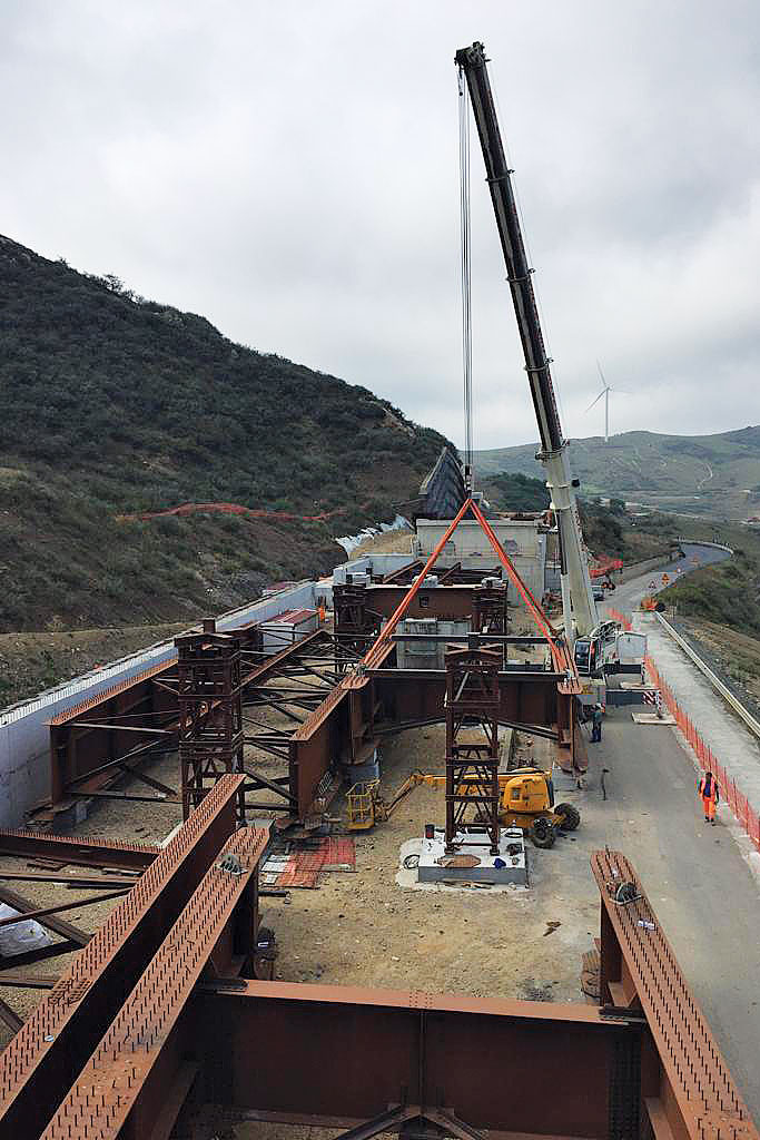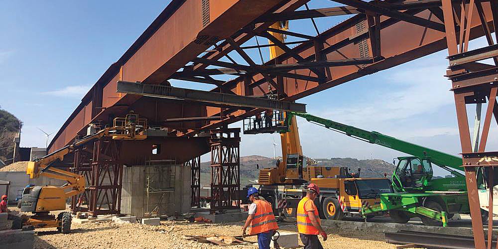
Project for the launch of the bridge.
Category: Road bridges
Services: Executive design
Period: July 2021 – August 2022
Client: IDRO.STRADE S.r.l
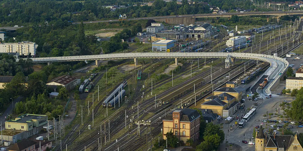
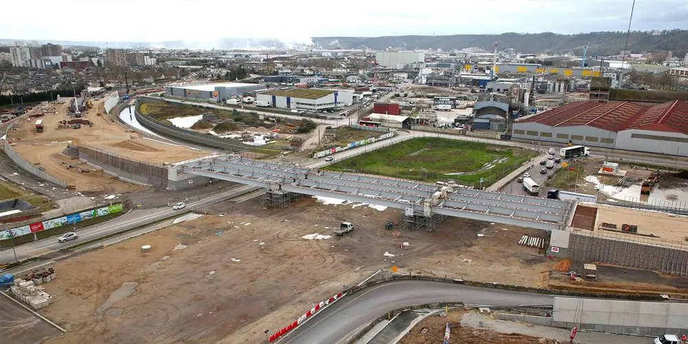
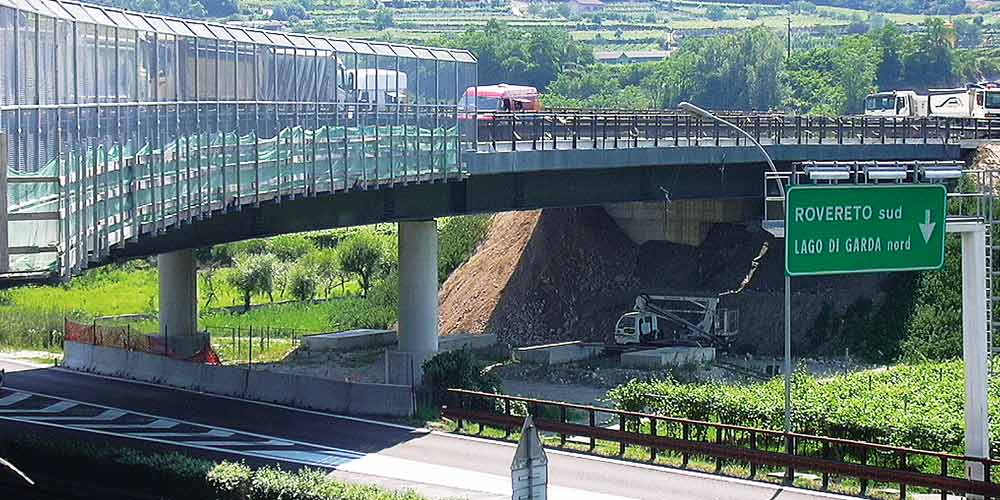
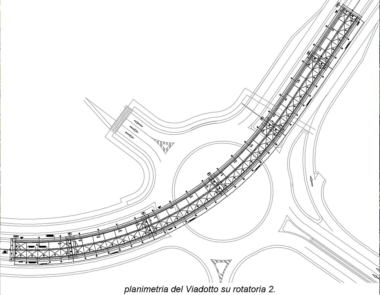
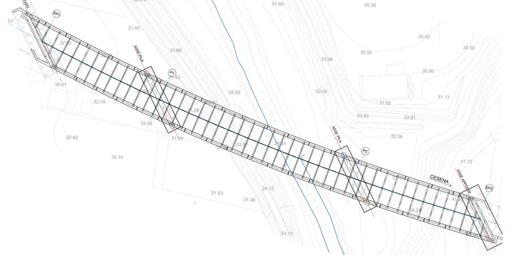
The viaduct over the Rabbi river is included in the section Km 1+930.59 and Km 2+141.67 of the new ring road system of Forlì, connecting the ring road East – Lot 3.
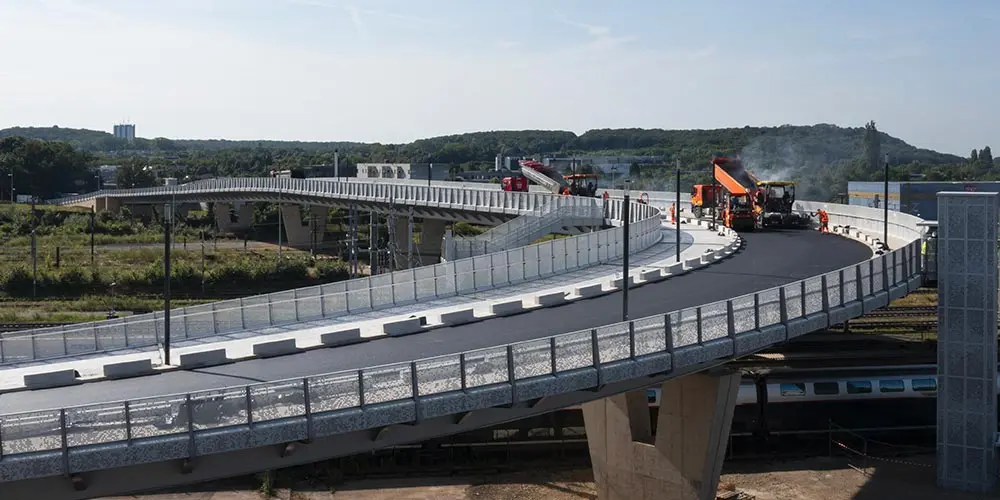
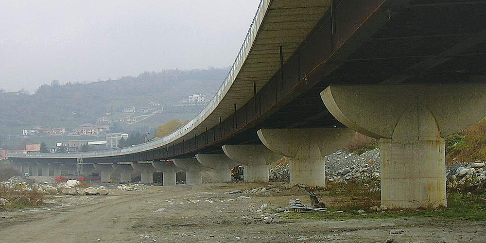
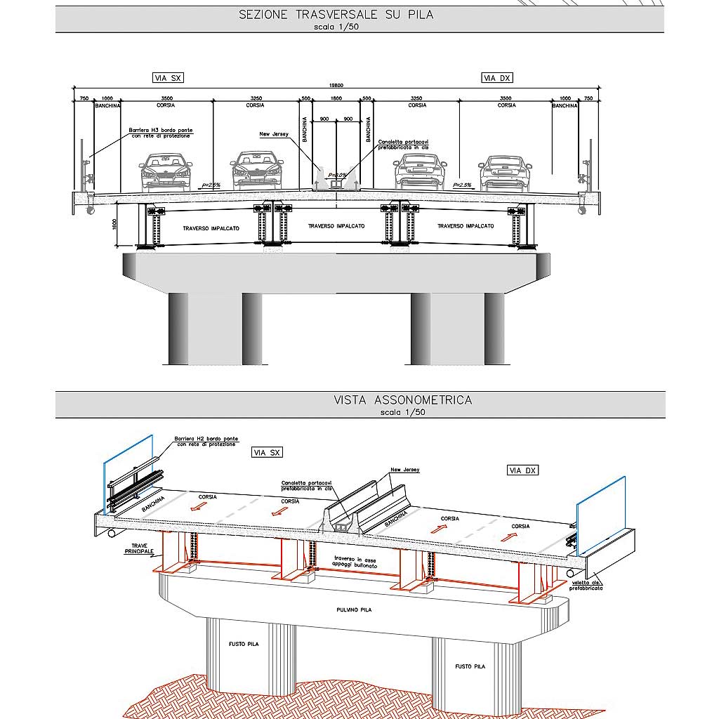
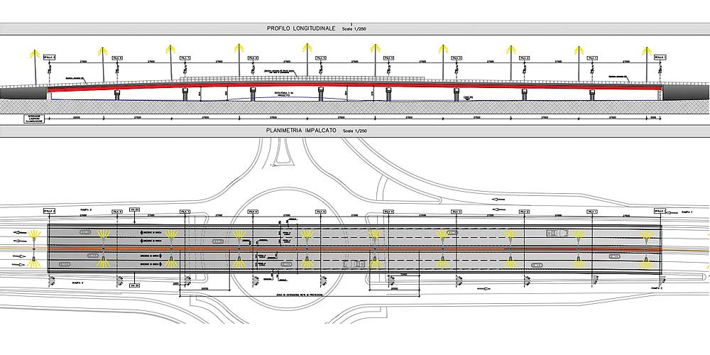
The work consists of a bridge over 3 spans of spans equal to 58.58, 94.30 and 58.20 m; it houses a road platform with a constant width of 10.5 m and two side curbs, on which a road safety barrier is mounted, with a width of 0.75 m; in addition to the curbs, there is a net space of 0.95 m used as a service sidewalk.
The viaduct over the Rabbi river is included in the section Km 1+930.59 and Km 2+141.67 of the new ring road system of Forlì, connecting the ring road East – Lot 3.
The work consists of a bridge over 3 spans of spans equal to 58.58, 94.30 and 58.20 m; it houses a road platform with a constant width of 10.5 m and two side curbs, on which a road safety barrier is mounted, with a width of 0.75 m; in addition to the curbs, there is a net space of 0.95 m used as a service sidewalk.
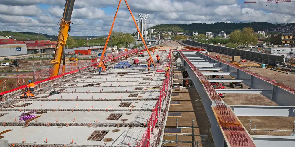
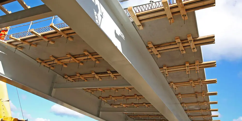
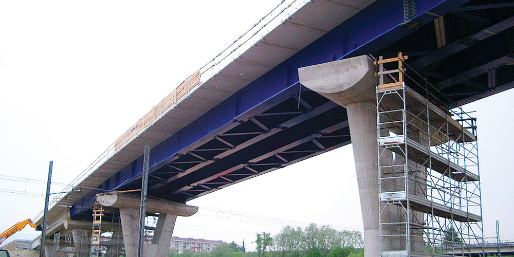
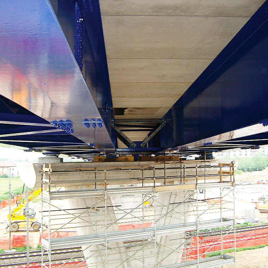
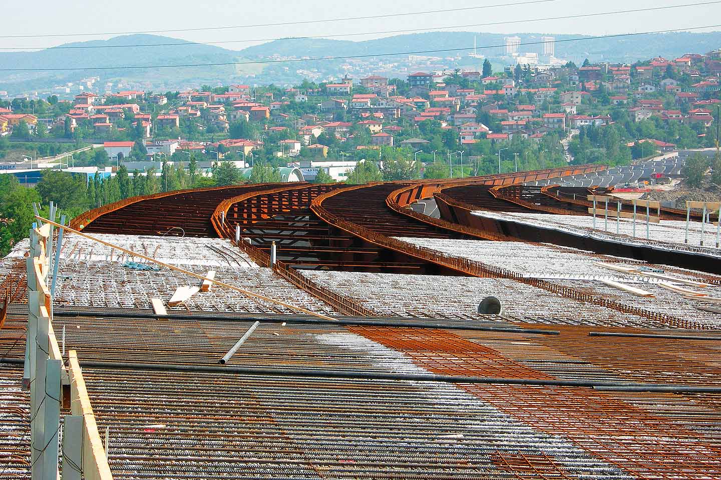
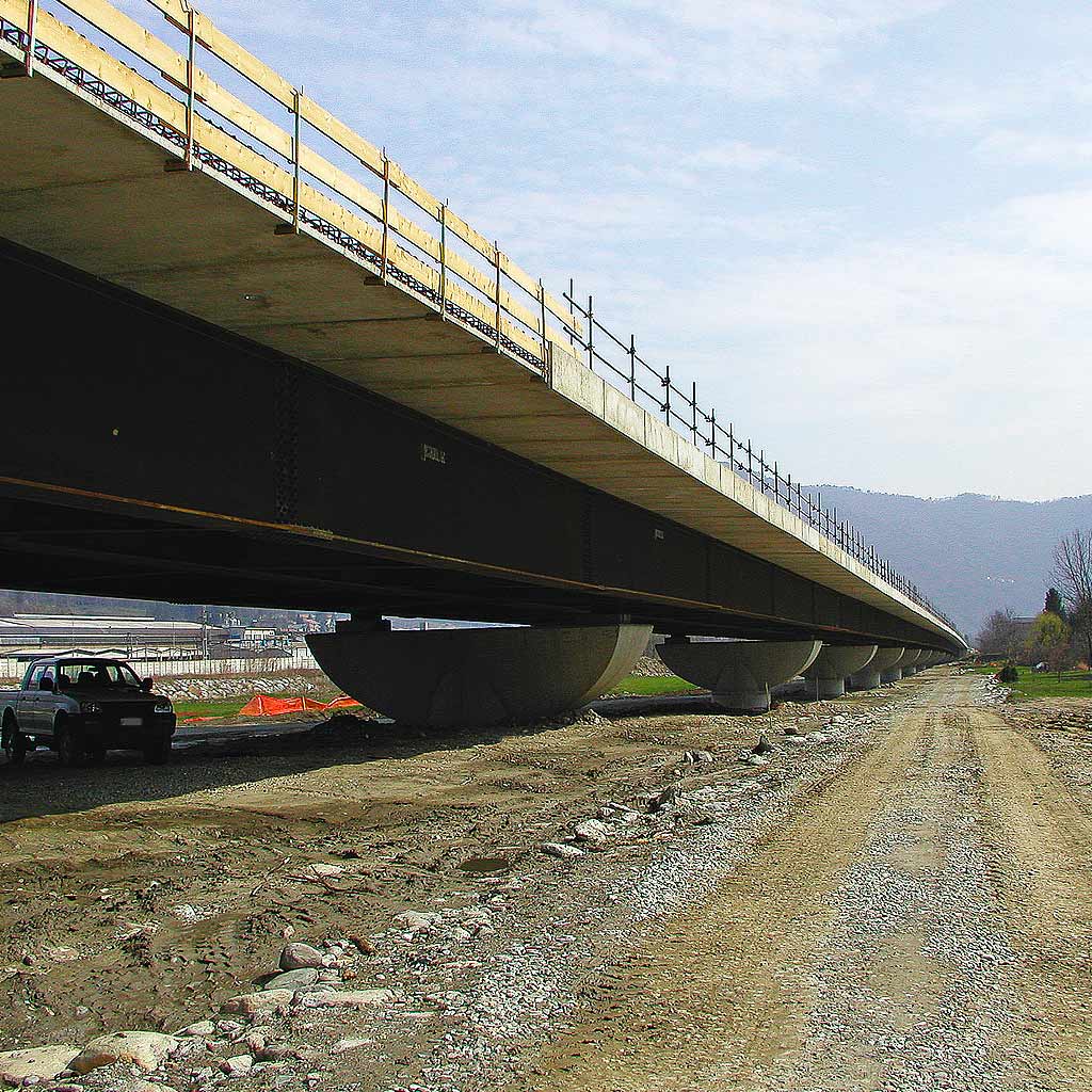
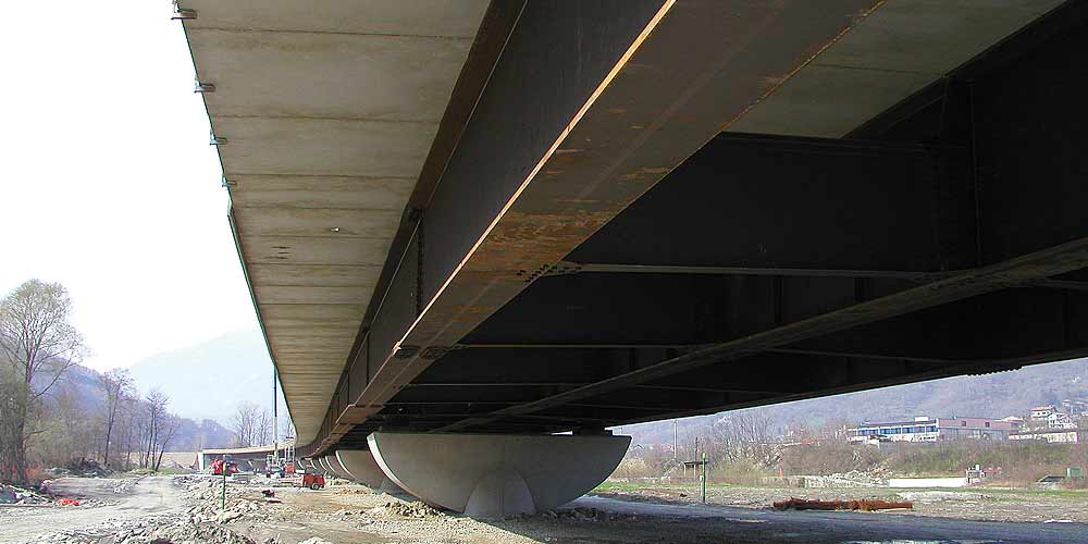
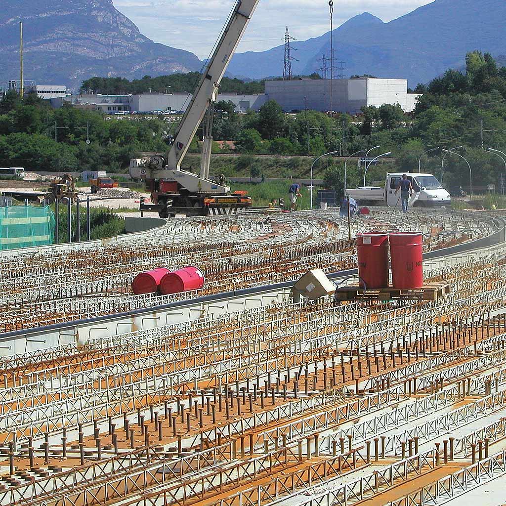
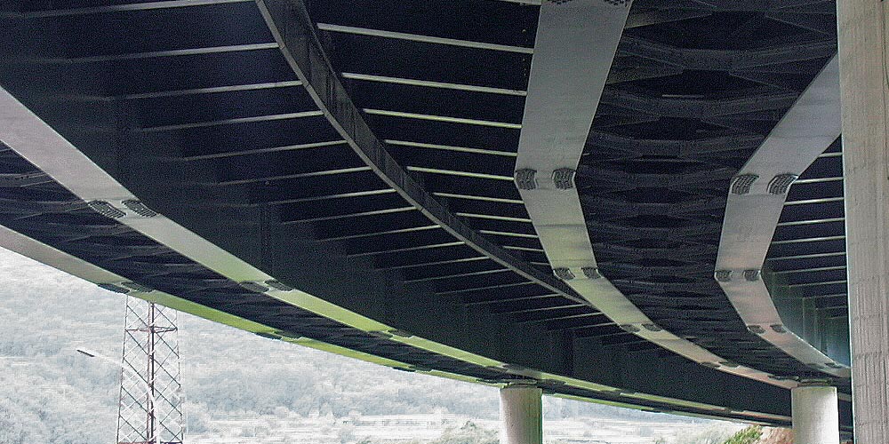
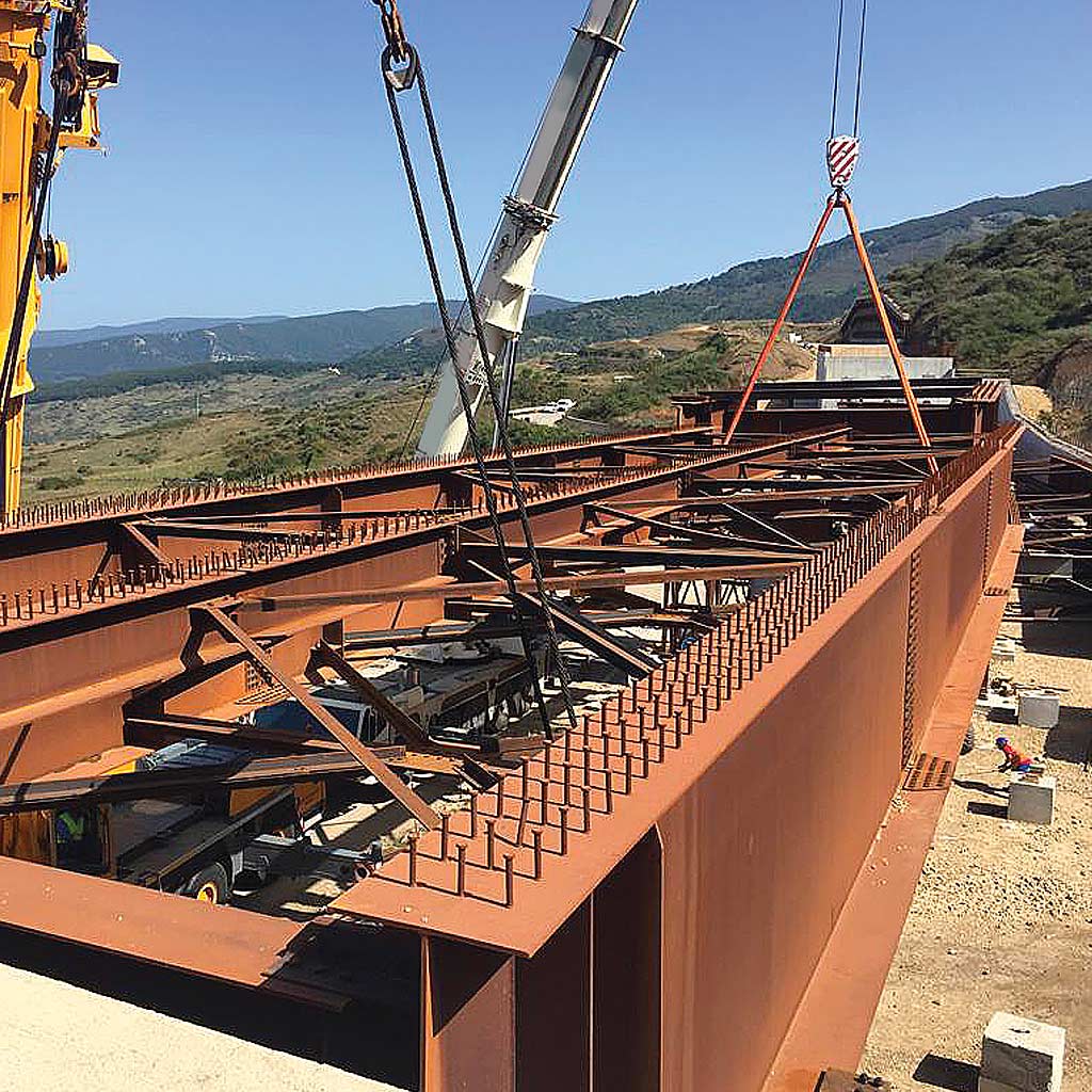
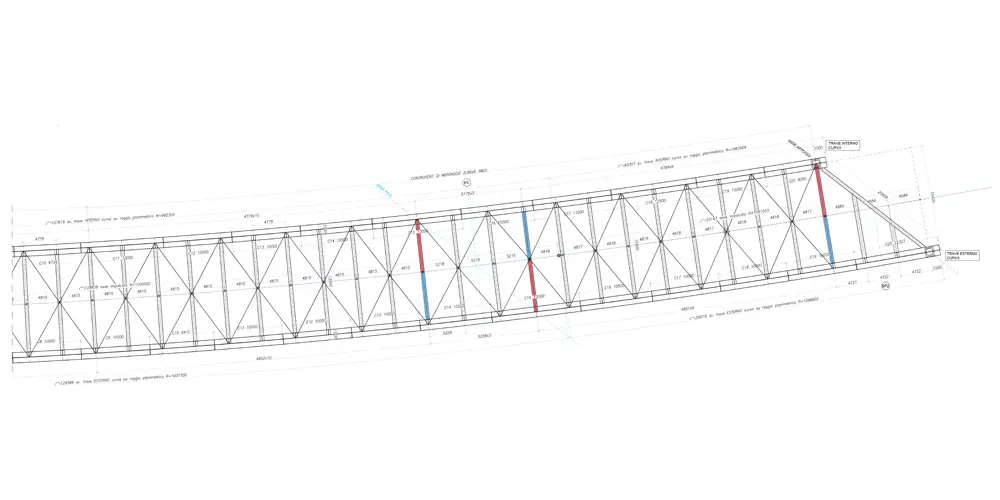
The structure consists of a grid of steel beams with two main beams arranged parallel along the development axis of the viaduct and by crosspieces orthogonal to the main beams with a regular pitch of about 5 m on which rests a roadway slab with a thickness equal to 21cm + 6cm of predalles. The two main metal beams have a double T cross section of variable height from 4 m (lowest value recorded in the span) up to 6.00 m (maximum value recorded in axis with the pile).
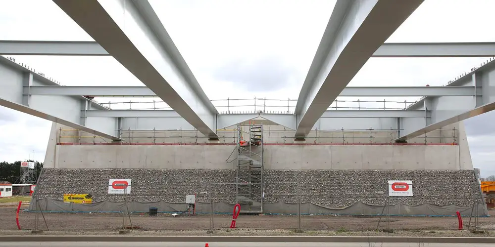
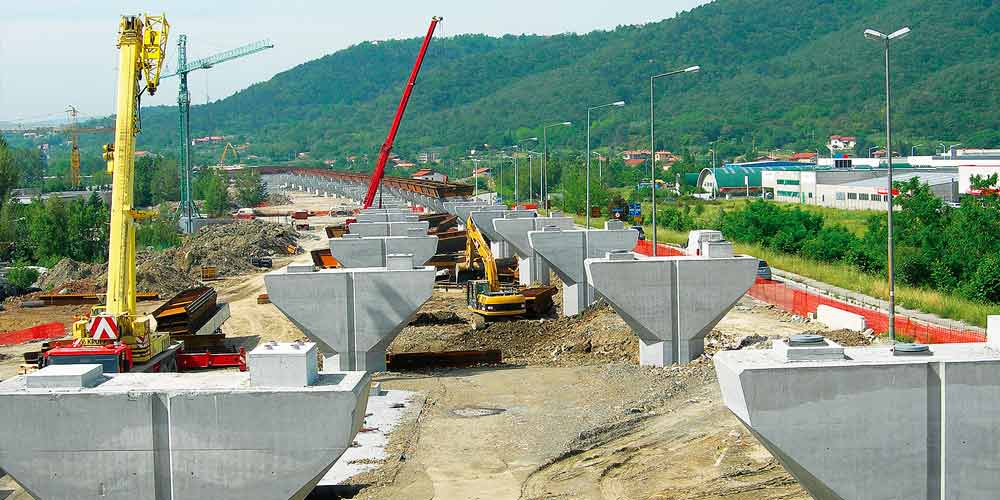
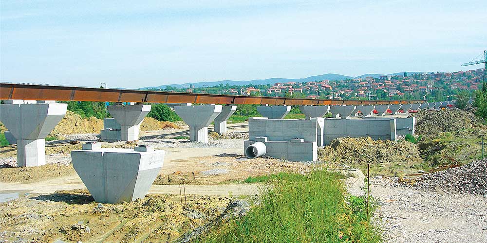
The bridge has 2 central reinforced concrete piers in which allow the Rabbi River to be crossed with the maximum span and two traditional reinforced concrete abutments.
The foundations of piers and abutments are made using 120 cm diameter piles with a length of 28 m for the abutments and 100 cm diameter piles and 30 m long for the piles.

The structure consists of a grid of steel beams with two main beams arranged parallel along the development axis of the viaduct and by crosspieces orthogonal to the main beams with a regular pitch of about 5 m on which rests a roadway slab with a thickness equal to 21cm + 6cm of predalles. The two main metal beams have a double T cross section of variable height from 4 m (lowest value recorded in the span) up to 6.00 m (maximum value recorded in axis with the pile).
The bridge has 2 central reinforced concrete piers in which allow the Rabbi River to be crossed with the maximum span and two traditional reinforced concrete abutments.
The foundations of piers and abutments are made using 120 cm diameter piles with a length of 28 m for the abutments and 100 cm diameter piles and 30 m long for the piles.