Launching beam project for the assembly of the new “Nichupte Bridge” viaduct.
Category: Special equipment
Services: Detailed Design – Executive Project of Main and secondary structures of the launching beam
Period: December 2022 – ongoing
Client: Deal

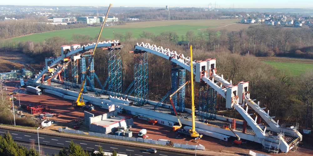
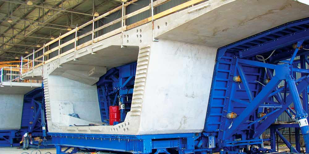
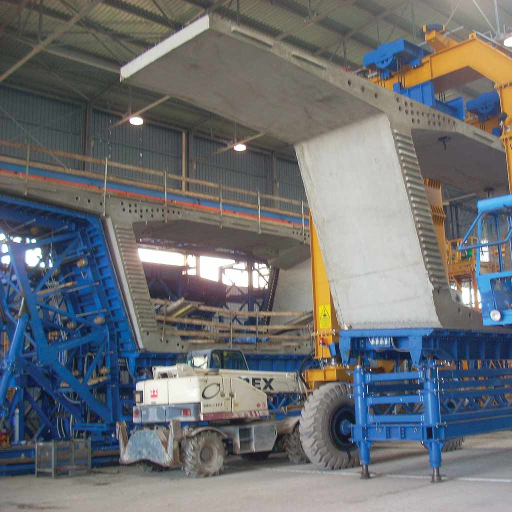
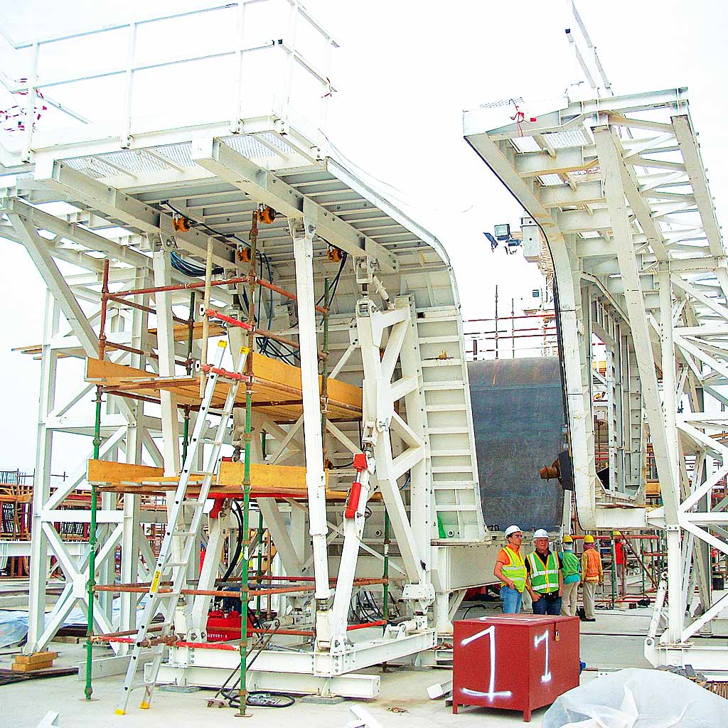
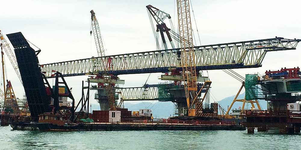
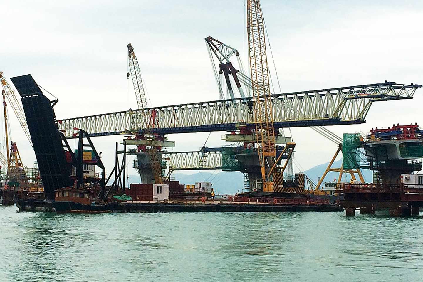
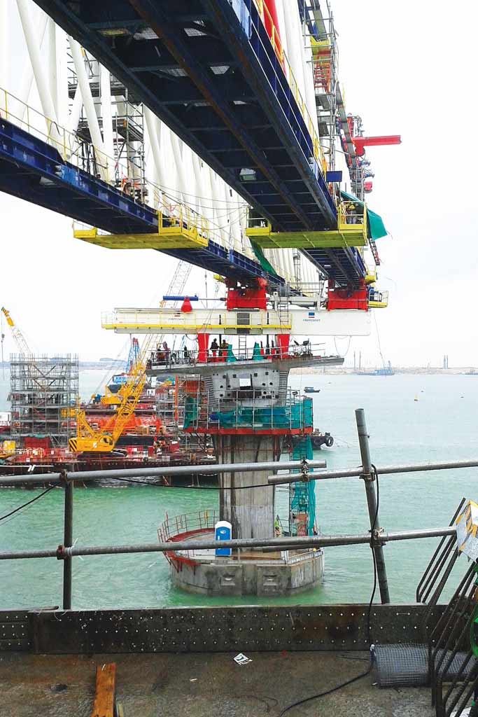
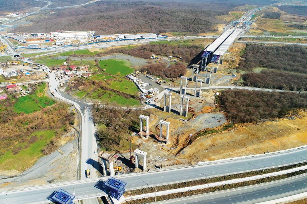
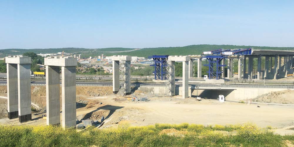
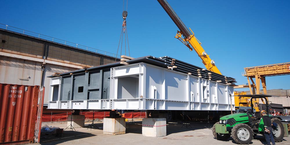
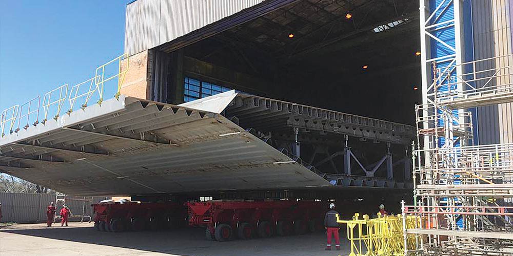
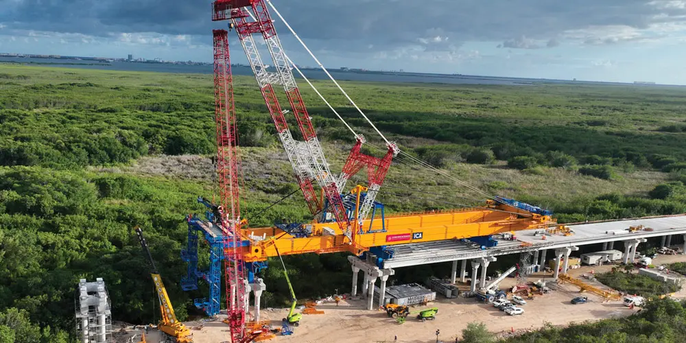
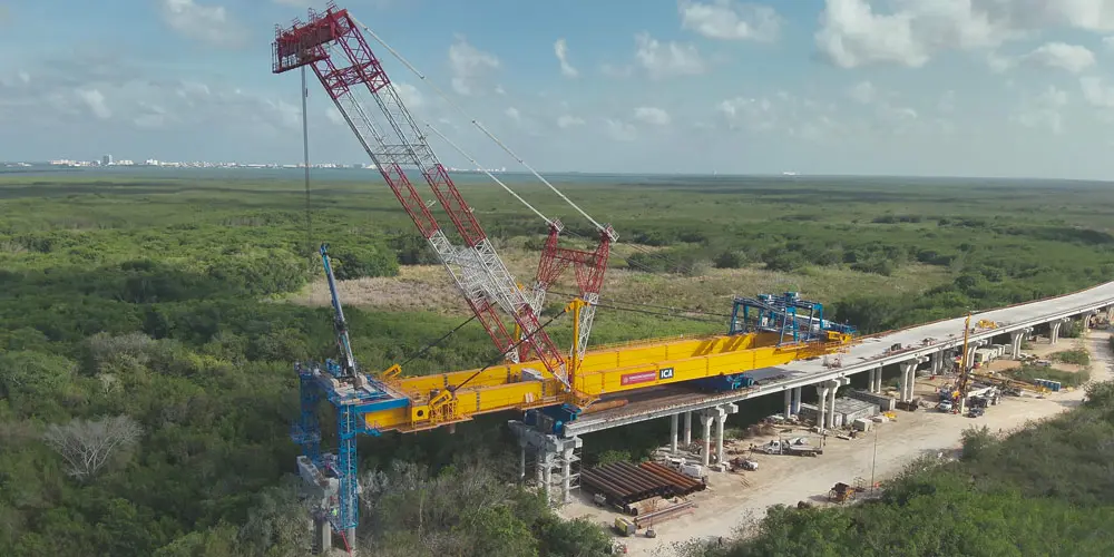
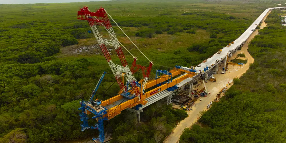
The Nichupte launching beam is a special piece of equipment designed for the assembly of the new “Nichupte Bridge” viaduct located in Cancun, Mexico. The purpose of the structure is to allow the construction of the foundations, the piers and the installation of the deck, composed of prefabricated concrete beams, without carrying out any construction site installation in the entire area of intervention of the equipment.
The Nichupte launching beam is a special piece of equipment designed for the assembly of the new “Nichupte Bridge” viaduct located in Cancun, Mexico. The purpose of the structure is to allow the construction of the foundations, the piers and the installation of the deck, composed of prefabricated concrete beams, without carrying out any construction site installation in the entire area of intervention of the equipment.
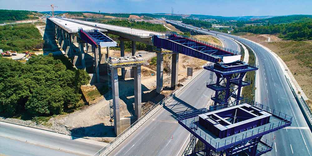
The machine is operational for the part of the viaduct between pier 40 and pier 60 (20 spans of approximately 35m), an area which, due to the presence of the lagoon below, does not provide for the possibility of construction site installations for environmental reasons.
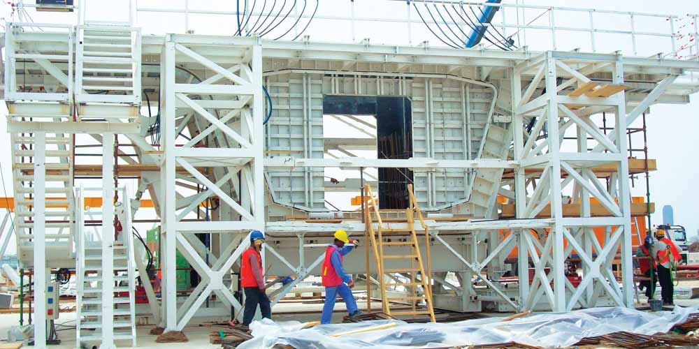
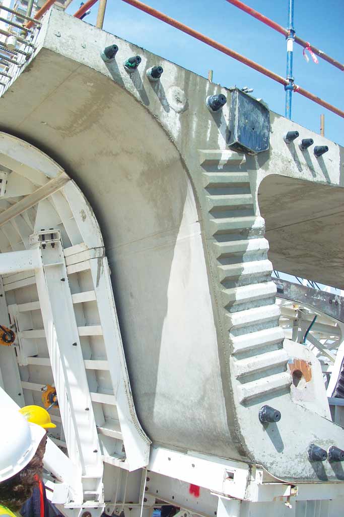
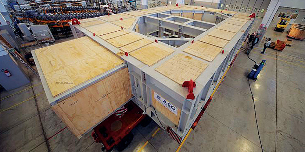
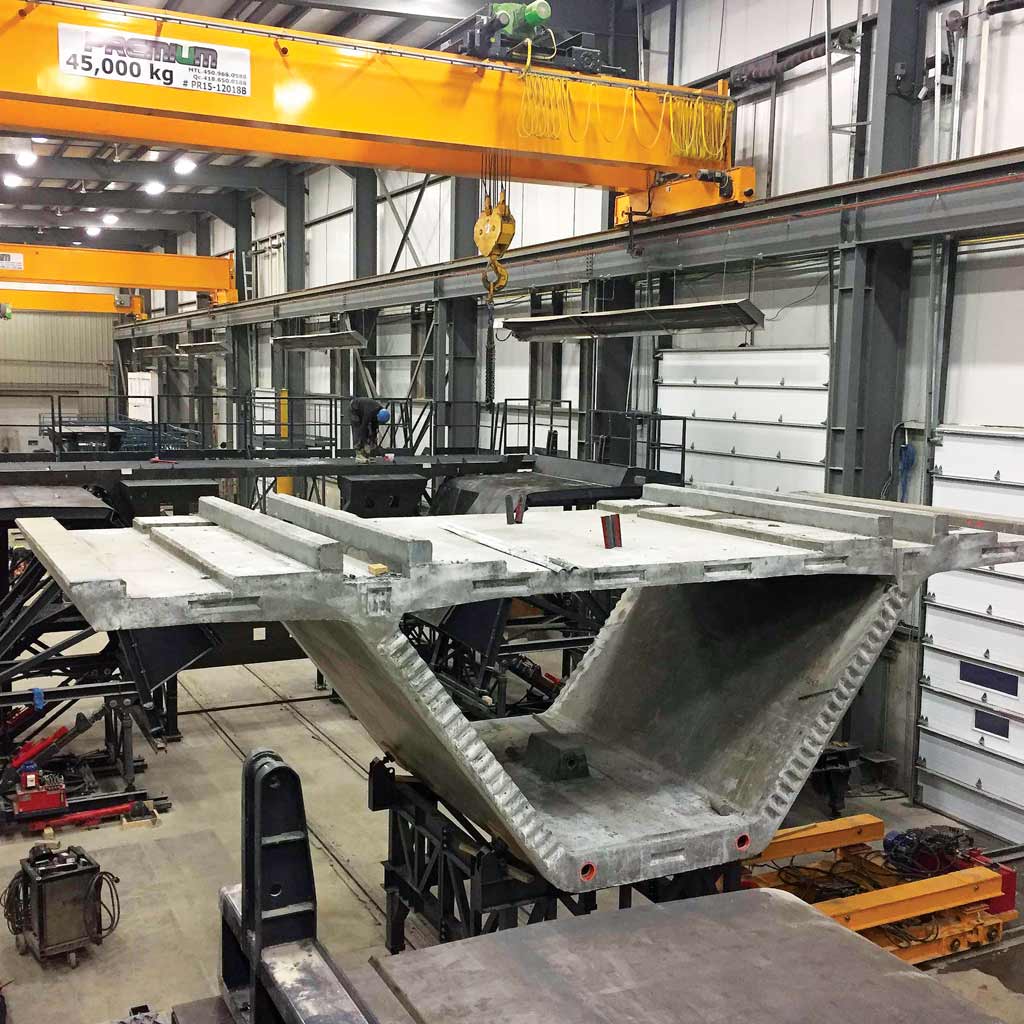
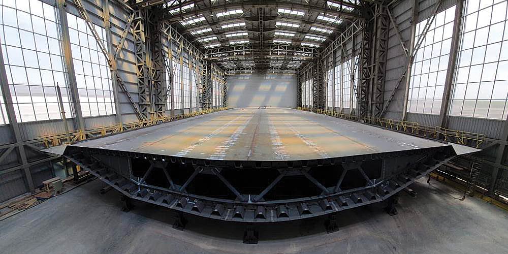
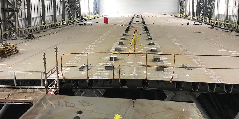
The launching beam is made up of two single-cell caissons of 96m in length. The boxes have an almost constant height of 3.22 m; only the first rear ashlar has a height of 2.82 m. There are ribbed slabs along the entire length both longitudinally and transversely. The diaphragms are placed with a constant pitch of approximately 3.8m.

The machine is operational for the part of the viaduct between pier 40 and pier 60 (20 spans of approximately 35m), an area which, due to the presence of the lagoon below, does not provide for the possibility of construction site installations for environmental reasons.
The launching beam is made up of two single-cell caissons of 96m in length. The boxes have an almost constant height of 3.22 m; only the first rear ashlar has a height of 2.82 m. There are ribbed slabs along the entire length both longitudinally and transversely. The diaphragms are placed with a constant pitch of approximately 3.8m.
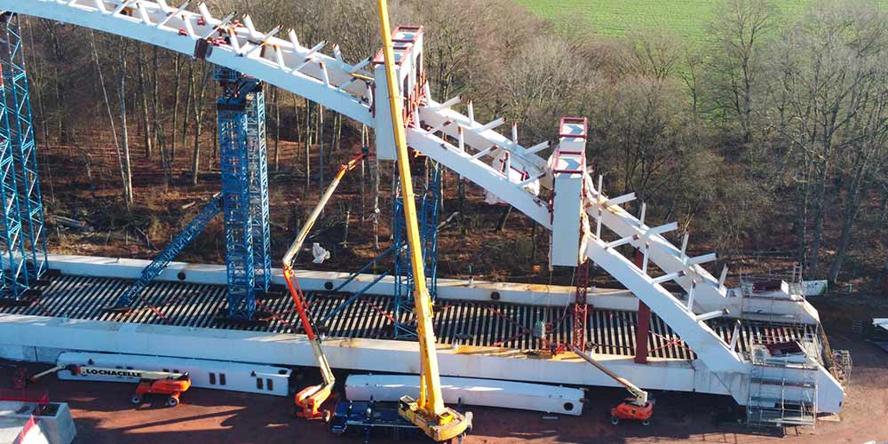
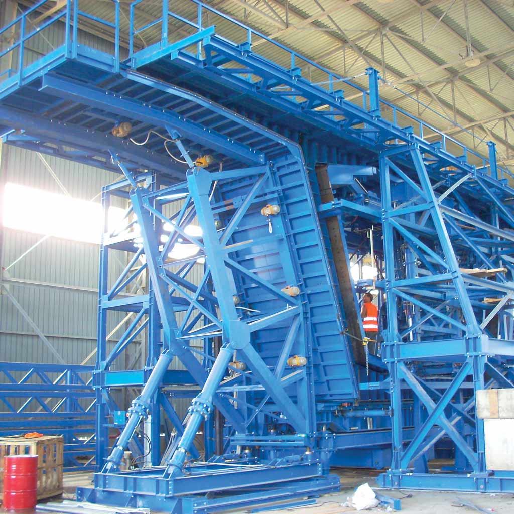
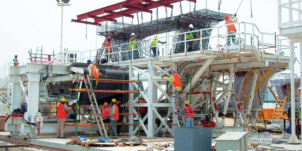
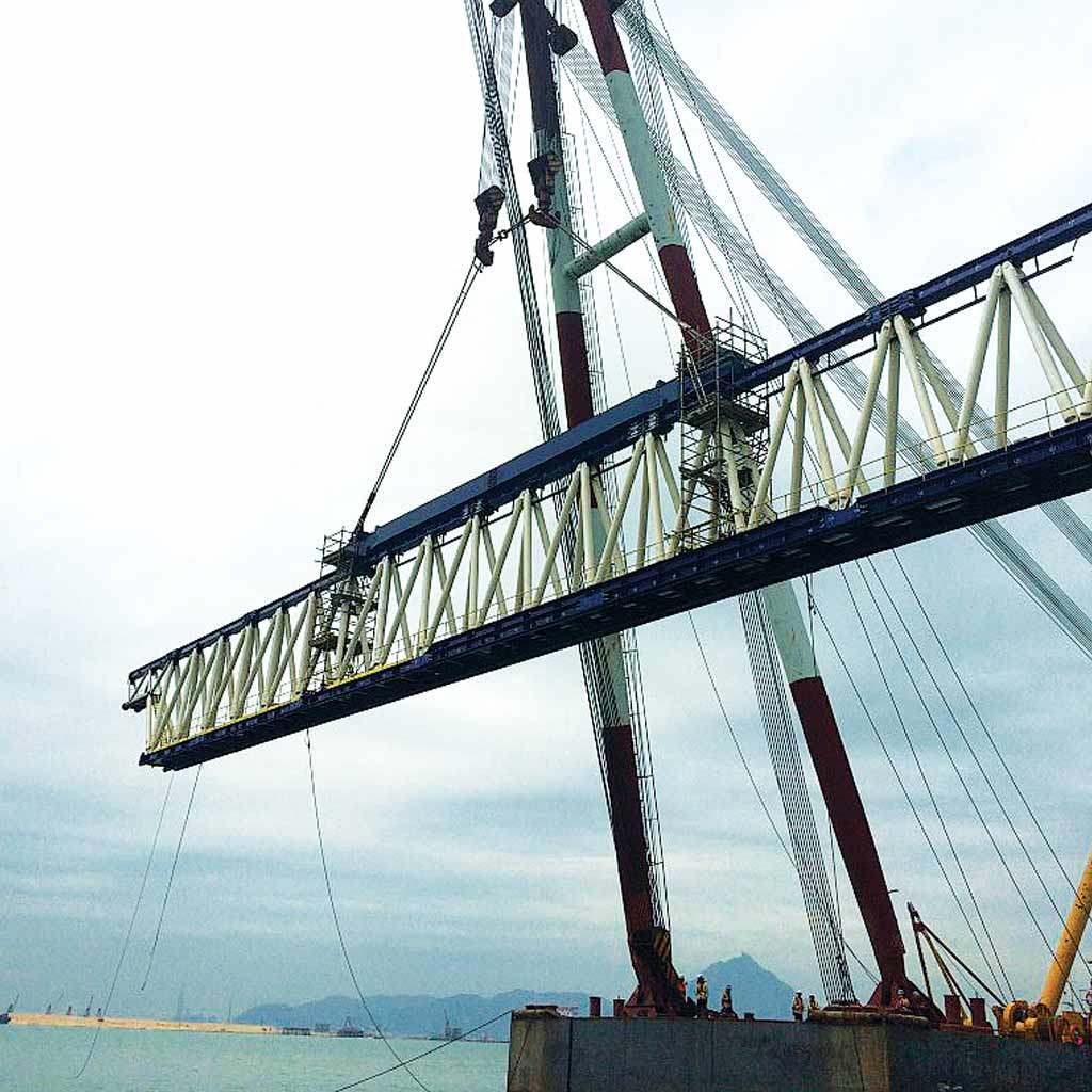
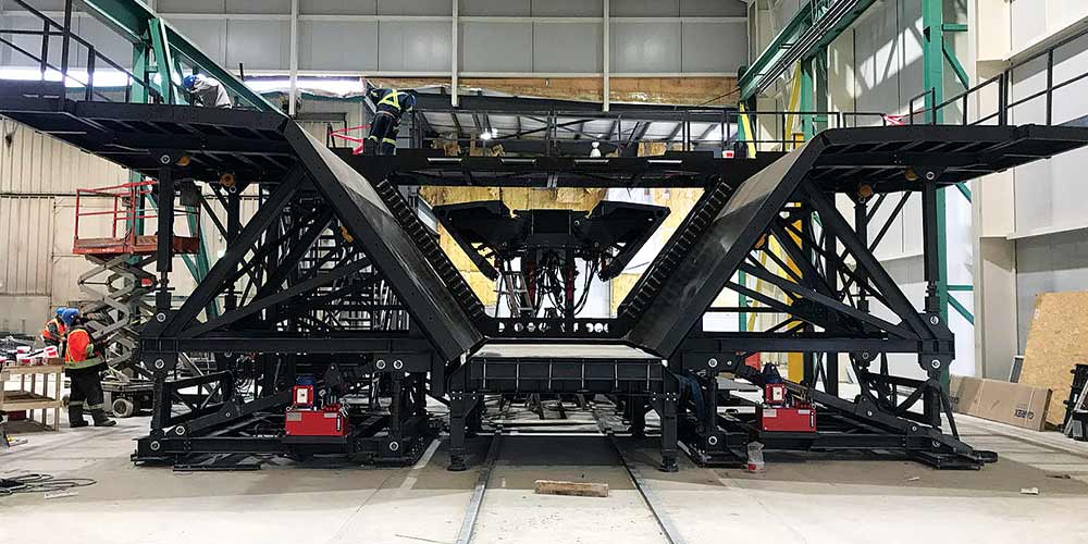
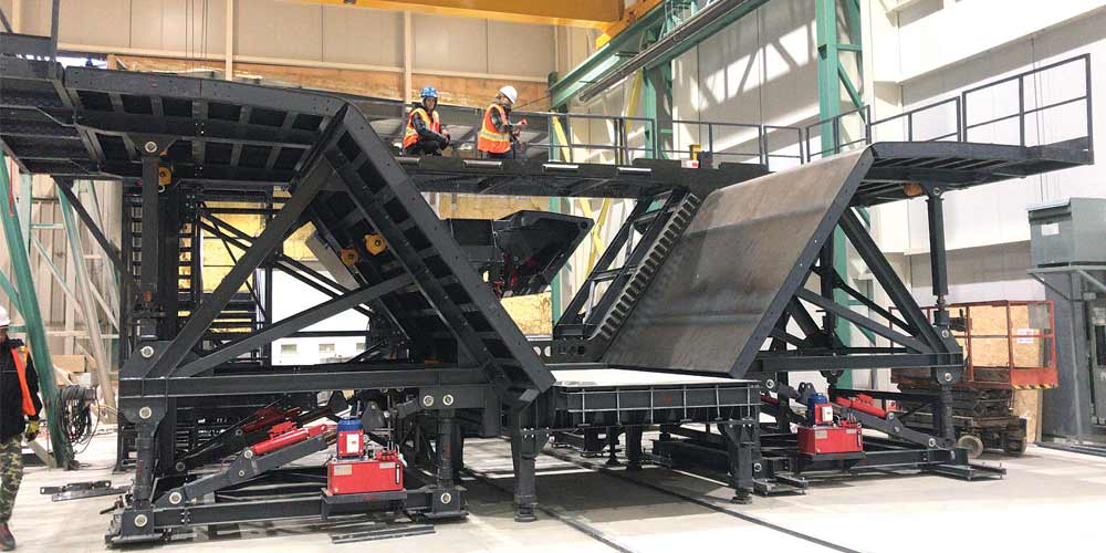
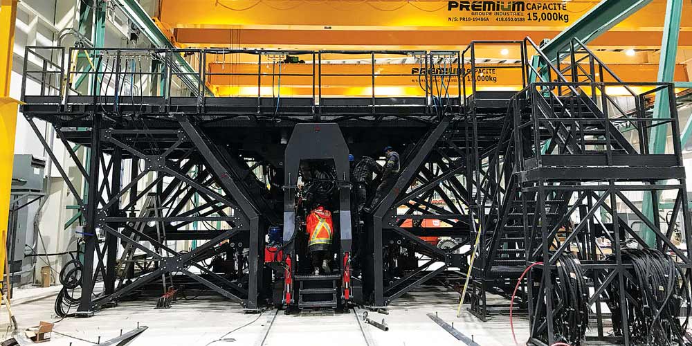
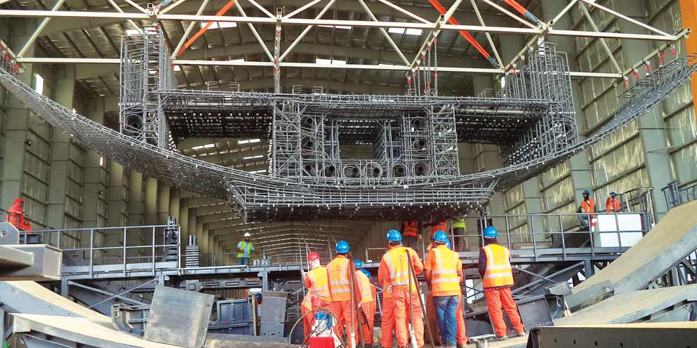
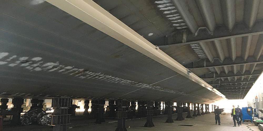
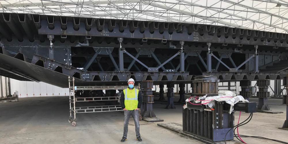
The main beams are connected transversely by n. 3 box-shaped crosspieces, one at the rear, one at two thirds of the span and one at the front.
The machine has a cable-staying system made up of 4 stays anchored at the top of the end crosspieces and at the top of the pylon located in correspondence with the central crosspiece.
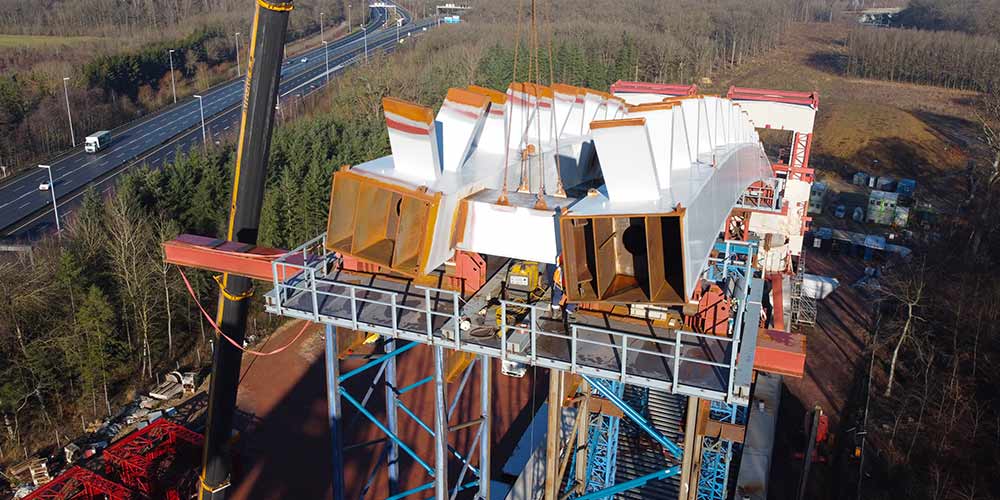
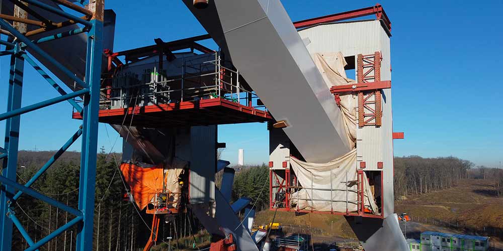
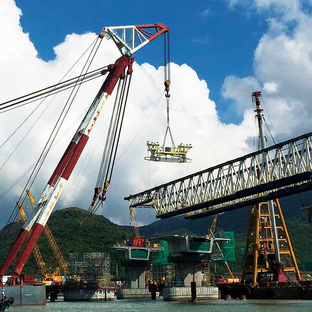
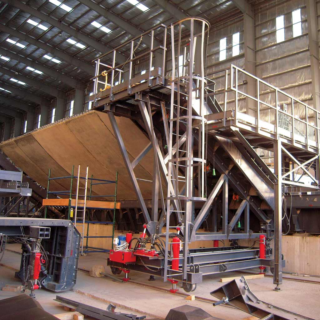
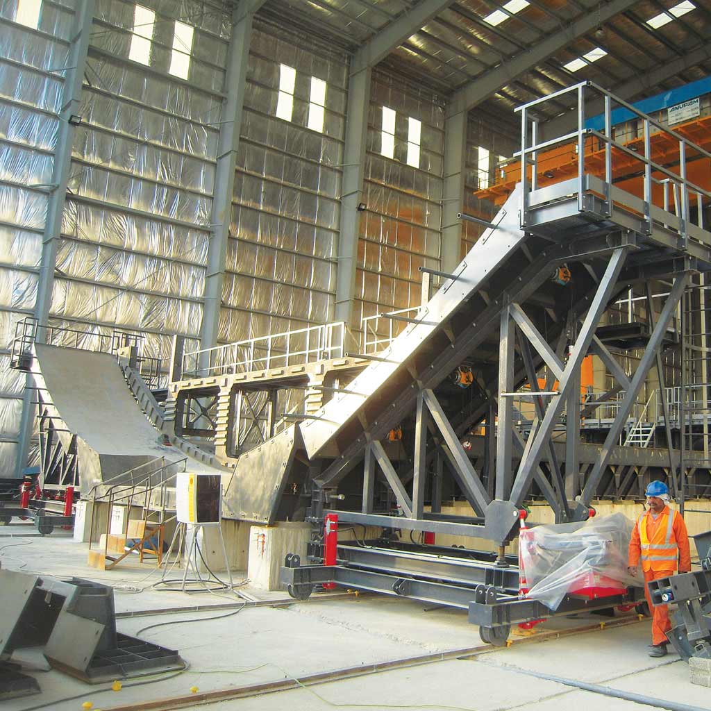
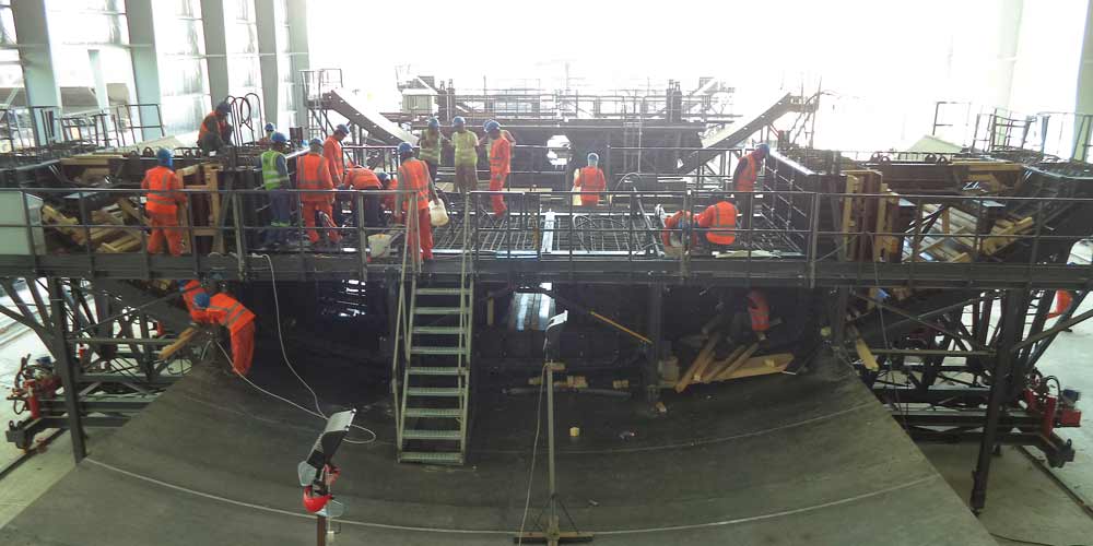
The structure is completed by the two platforms, a rear one which houses the generators and guarantees access to the entire rear part (main access to the machine and inspection of the containers), and a front one where all the construction site activities are carried out. The various work levels are connected to each other via external walkways and stairs.
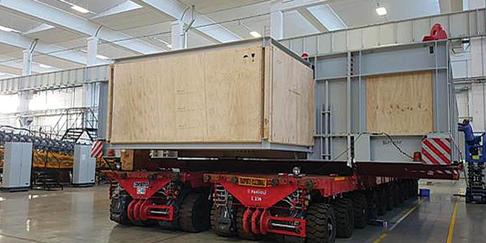
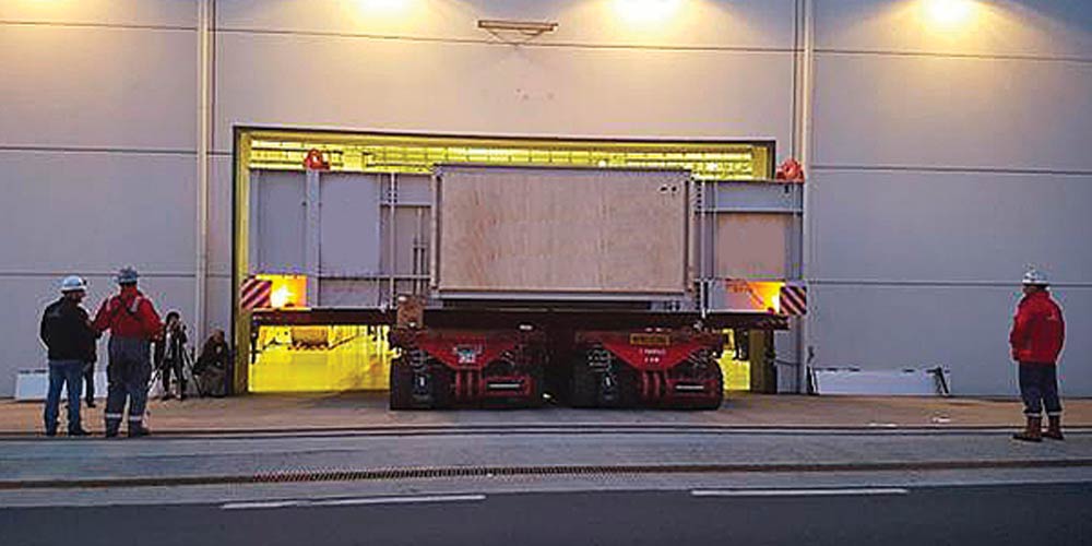
The overall size outside the wagon is 101×25.7×17.4m
The structure is completed by the two platforms, a rear one which houses the generators and guarantees access to the entire rear part (main access to the machine and inspection of the containers), and a front one where all the construction site activities are carried out. The various work levels are connected to each other via external walkways and stairs.
The overall size outside the wagon is 101×25.7×17.4m